48 - 8630
INSTALLATION
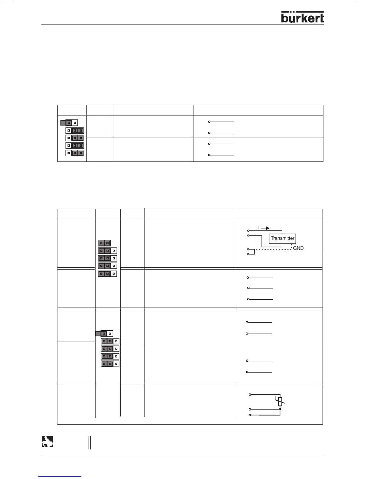
➔ Select using the jumpers:
2 binary outputs (see terminal
Allocation when binary outputs selected
) or
Process value input (see terminal
Allocation when process value input selected
).
Terminals 7 to 10 are connected to the corresponding signals.
➔ The input type is set via the configuration menu (see
Procedure for specifying the basic settings
).
Choice of binary outputs or process value input
Input type* Jumper Terminal Allocation External connection
4 ... 20 mA 7 + 24 V input transmitter
internal 8 Output transmitter
supply 9 Bridge to GND (GND from
3-conductor transmitter)
10 GND
Frequency 7 + 24 V supply sensor
internal 8 Clock input +
supply 9 not connected
10 Clock input - (GND)
4 ... 20 mA 7 not connected
external 8 Process actual +
supply 9 Process actual -
10 not connected
Frequency 7 not connected
external 8 Clock input +
supply 9 not connected
10 Clock input -
Pt-100 7 not connected
(see 8 Process actual 1 (current supply)
Note 9 Process actual 2 (compensation)
below) 10 Process actual 3 (GND)
7
+ (4 ... 20 mA)
8
9 GND
Clock +
8
10
Clock -
Clock - (GND)
10
8
7 +24 V
Clock +
8
Terminal allocation on selection of process value input:
Jumper Terminal Allocation External connection
7 Binary output 1
8 Binary output 1
9 Binary output 2
10 Binary output 2
8
7
9
10
24 V / 0 V NC / NO
GND
24 V / 0 V NC / NO
GND
For reasons of line compensation, connect the Pt 100 sensor over 3 conductors. Be sure
to bridge terminals 9 and 10 at the sensor.
NOTE
8
10
9
Pt100
9
10