8630 - 47
INSTALLATION
* Electrical connection - terminals for cable bushing
➔ Remove the cover with the cable bushings to gain
access to the screw terminals. This is done by
unscrewing the 4 self-tapping screws.
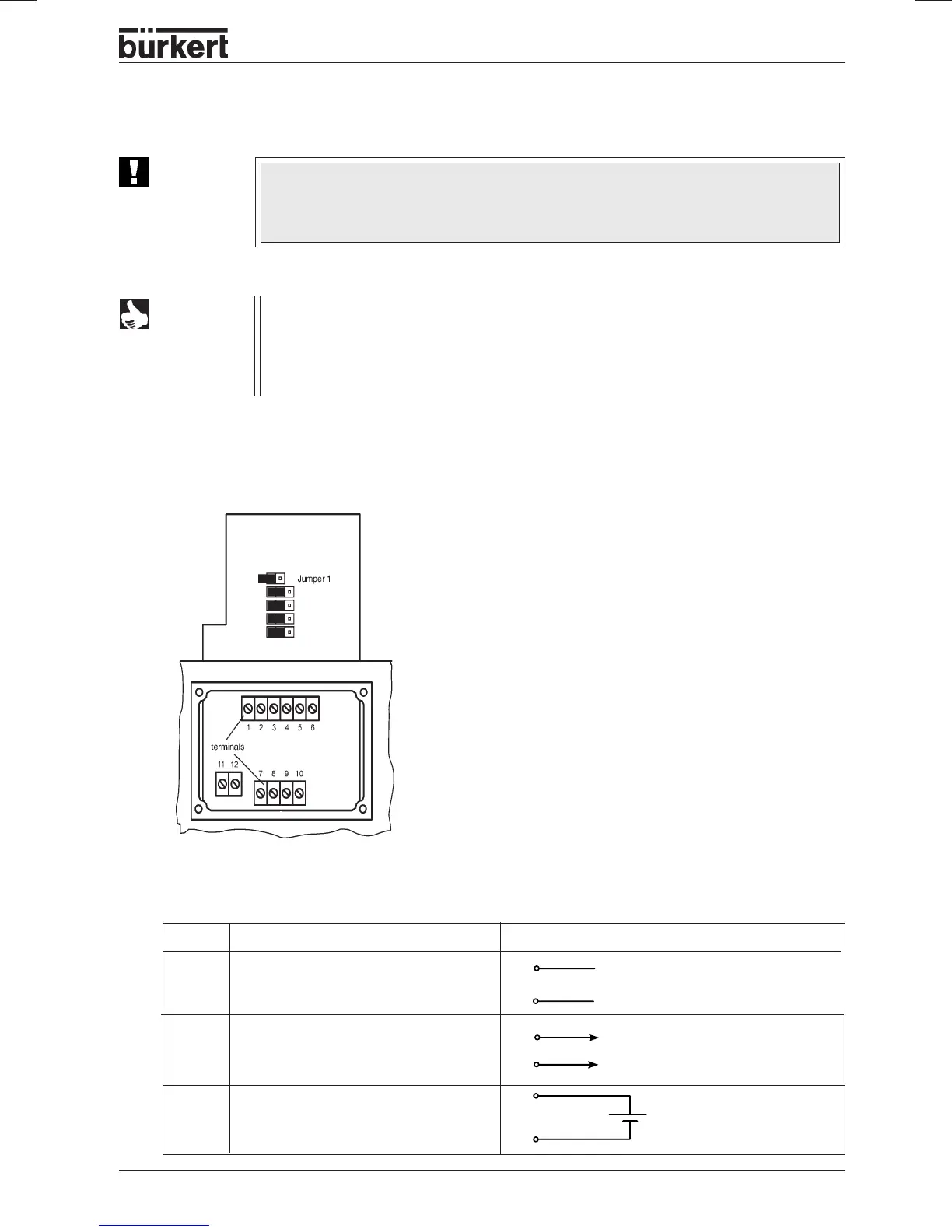
Connection PCB of the TOP Control
Continuous with screw
terminals and jumpers
Terminal Allocation External connection
1 Setpoint +
2 Setpoint GND
3 Analog position feedback +
4 Analog position feedback GND
5 Operating voltage +
6 Operating voltage GND
24 V DC ± 10 %
max. residual ripple 10 %
2
1
+ + (0/4 ... 20 mA or 0 ... 5/10 V
GND
5
6
Terminal configuration with cable bushings
GND
3
4
+ (0/4 ... 20 mA or 0 ... 5/10 V)
completely isolated electrically
ATTENTION!
Use of the 4 - 20 mA setpoint input
If the voltage supply of a TOP Control Continuous device fails in a row of such devices
connected in series, the input of the failed device will become high-impedance. This will
cause the 4 - 20 mA standard signal to fail. If this occurs, please contact Bürkert Service
directly.
NOTE
For connection to the technical earth (ground) (TE), a threaded stud with nut is
provided on the connection module. To assure electromagnetic compatibility
(EMC), connect this stud to a suitable earthing (grounding) point using as short a
cable as possible (max. 30 cm).