8630 - 35
FIRST COMMISSIONING
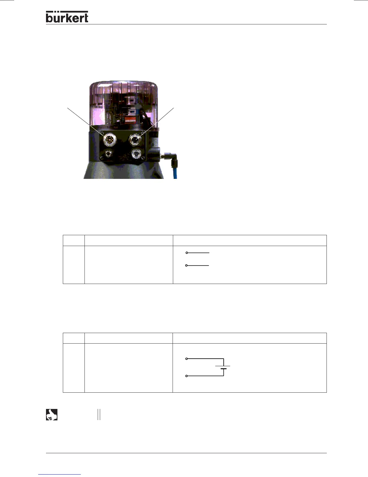
* Electrical installation - multipole connector
Configuration of the circular connector M 12
Pin Allocation External connection
1 + 24 V
2 not connected
3 GND
4 not connected
24 V DC ± 10 %
max. residual ripple 10 %
A
B
+ (0/4 ... 20 mA or 0 ... 5 / 10 V)
GND
3
1
M12M16
After application of the supply voltage, the TOP Control
Continuous is in operation. Carry out the
necessary basic settings and initiate self-parametrization of the TOP Control.
➔ Apply the setpoint signal to the circular
connector M16
➔ Apply the supply voltage to the circular connector M12
Configuration of the circular connector M 16
Allocation
Setpoint + (0/4 ... 20 mA
or 0 ... 5/10 V)
Setpoint GND
External connection/Signal levelPin
B
A
NOTE
Further installation notes are to be found in the chapter
Installation
.