46 - 8630
INSTALLATION
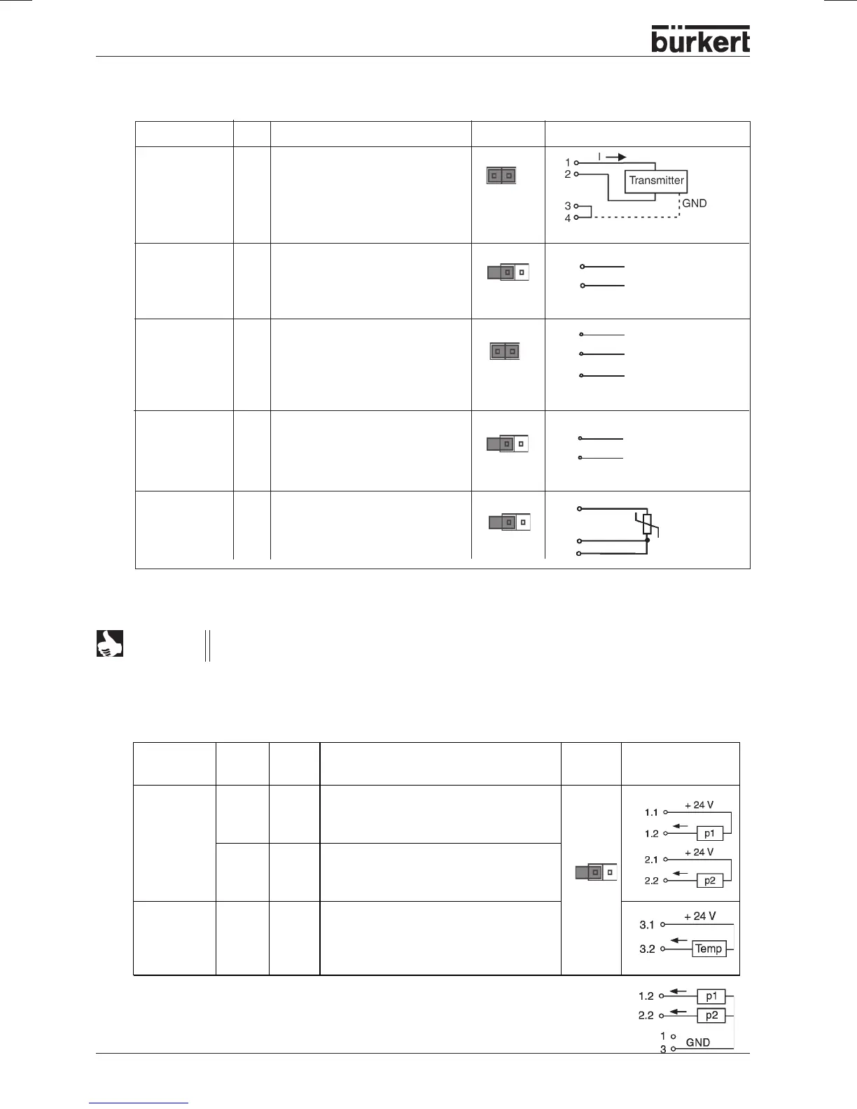
Input type No. of
plugs
Pin Configuration Jumper ext. connection
internally
supplied
transmitter*
11
2
3 + 4
+ 24 V - supply to transmitter p1
4 ... 20 mA - output from transmitter p1
n.c.
21
2
3 + 4
+ 24 V - supply to transmitter p2
4 ... 20 mA - output from transmitter p2
n.c.
Option:
temperature
transmitter
31
2
3 + 4
+ 24 V - supply to transmitter
4 ... 20 mA - output from temperature
transmitter
n.c.
* May be set via software (section
Procedure for specifying the basic settings
)
** The jumper is situated on the connection board of the TOP Control Continuous (see next page)
Process value (circular plug M 8)
For line compensation reasons, connect sensor Pt-100 via 3 conductors. PIN 3 and PIN 4
must be bridged at the sensor.
NOTE
Process value with the option flow rate controller (2 circular plugs M8)
Option: with temperature sensor input (3 circular plugs M8)
Input type * Pin Allocation Jumper** External connection
4 ... 20 mA 1 + 24 V supply transmitter
- internal 2 Output Transmitter
supply 3 GND
4 bridge to GND (GND from
3-conductor transmitter)
4 ... 20 mA 1 not connected
- external 2 Process actual +
supply 3 not connected
4 Process actual -
Frequency 1 + 24 V - supply sensor
- internal 2 Clock input +
supply 3 Clock input - (GND)
4 not connected
Frequency 1 not connected
- external 2 Clock input +
supply 3 Clock input -
4 not connected
Pt-100 1 not connected
(see 2 process actual 1(current supply)
Note 3 process actual 3 (GND)
below) 4 process actual 2 (compensation)
2
4
Pt 100
Clock +
Clock -
Clock +
Clock -
3
2
1
+24 V
2
3
3
* With external supply of the sensors, the mass of the standard signal must be
connected to the mass of the supply voltage.
Circular plug
M12
2
4
4 ... 20 mA
GND