138 - 8630
DEVICENET
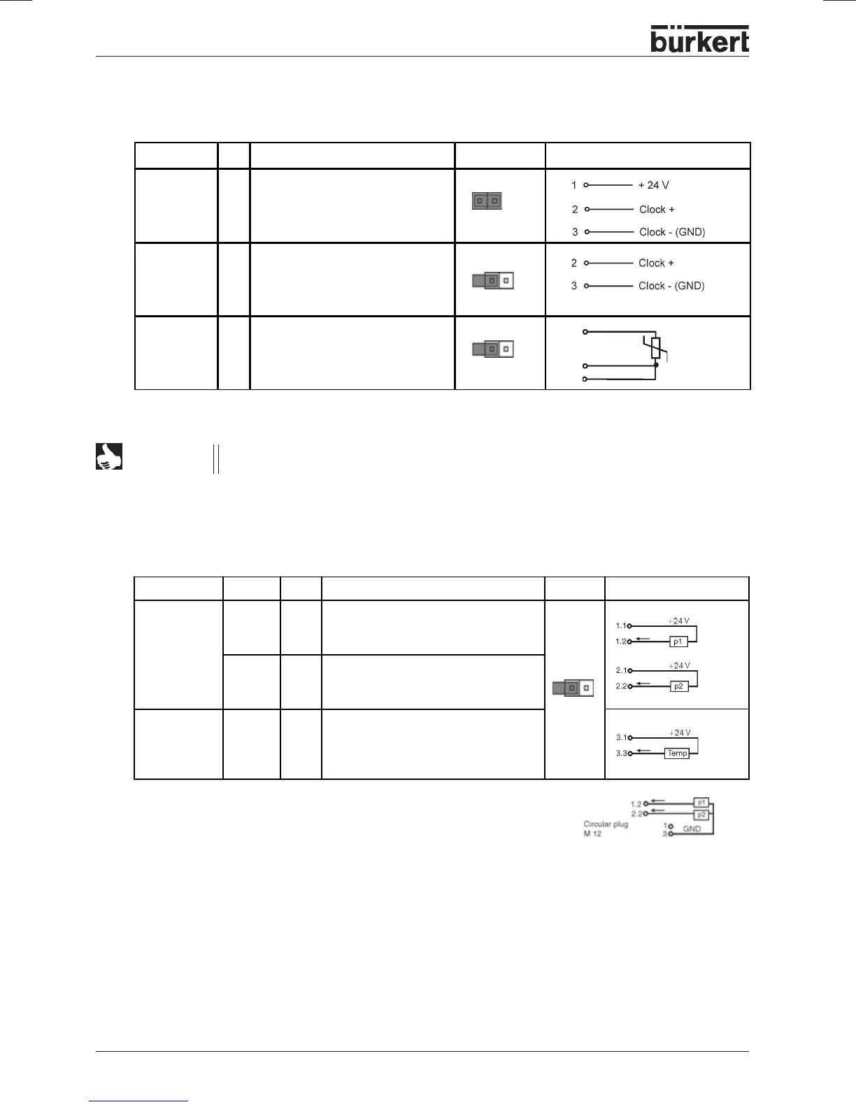
Input type * Pin Assignment Jumper external circuit
Frequency
internally
supplied
1
2
3
4
+ 24 V supply sensor
clock input +
not assigned
clock input - / GND
Frequency
externally
supplied
1
2
3
4
not assigned
clock input +
not assigned
clock input -
Pt-100 (see
Note)
1
2
3
4
not assigned
process actual 1 (current supply)
process actual 2 (GND)
process actual 3 (compensation)
*
adjustable via software
Process value (circular plug M8, continuation)
For line compensation reasons, connect sensor Pt-100 via three conductors. PIN3 and 4
must be bridged at the sensor.
NOTE
Termination connection for DeviceNet systems
On installing a DeviceNet system, it is important to have the correct termination circuit for the data lines.
The circuit avoids the occurrence of faults through signal reflections on the data lines. For this purpose
the main line is to be terminated at both ends with resistors of respectively 120 Ω and 1 / 4 W power
loss.
Pt100
2
3
4
Actual process value for the fluid flow controller option (2 M8 round
plugs), or optionally: with temperature sensor input (3 M8 round
plugs)
* With external supply of the sensors the mass of the standard
signal must be connected with the mass of supply voltage.
Input type Plug Pin Assignment Jumper external circuit
internally
supplied
transmitter*
11
2
3 + 4
+ 24 V - transmitter supply p1
4 ... 20 mA - transmitter output p1
not assigned
21
2
3 + 4
+ 24 V - transmitter supply p2
4 ... 20 mA - transmitter output p2
not assigned
option:
temperature
transmitter*
31
3
2 + 4
+ 24 V - transmitter supply
4 ... 20 mA - output
transmitter temperature
not assigned