User Manual – Rev AJ California Instruments
2.1.2 Output
Note: All specifications are for AC and DC unless otherwise indicated.
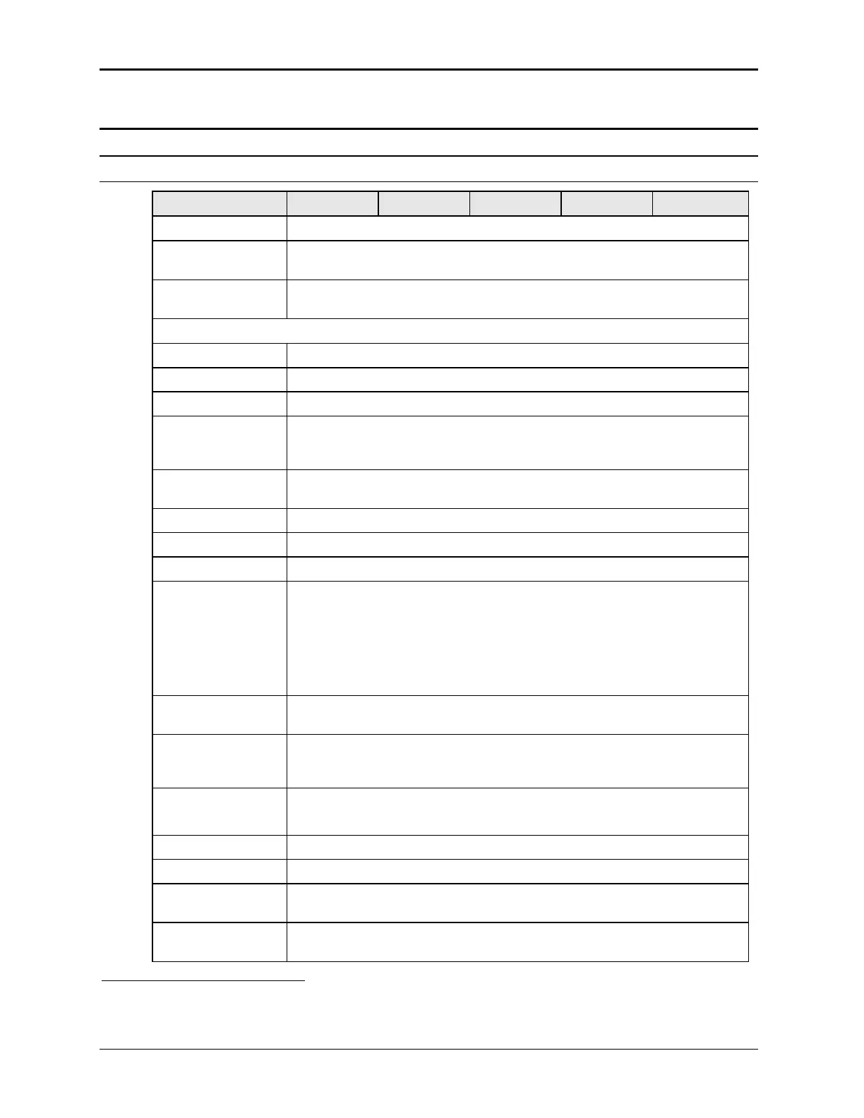
Output Parameter MX30 MX45 MX60 MX90 MX135
Modes
Std
Controller
AC, DC
Pi
Controller
AC, DC, AC+DC
Voltage:
Ranges (L-N):
AC Mode Low: 0 - 150 V / High: 0 - 300 V
DC Mode Low: 0 - 200 V / High: 0 - 400 V
AC+DC Mode AC: Low: 0 - 150 V / High: 0 - 300 V
DC Offset: Low Vrange: 0 - 150 V
High Vrange: 0 - 220 V (Series II) / High; 0 – 250 V (Series I).
Note:
On MX units with standard controller, only one voltage range is available unless
the -R range change option is installed.
Resolution:
AC Mode 0.1 V
DC Mode 0.1 V
AC+DC Mode AC: 0.1 V
DC Offset:
Series I 0.01 V < 2.5 V
0.1 V 2.5 - 25 V
1 V > 25 V
Series II 0.01 V
Accuracy: ± 0.3 V AC mode
± 1 V DC mode
Distortion THD
1
:
(Resistive full load)
< 1 % @ 16 - 66 Hz
< 2 % @ 66 - 500 Hz
< 3 % @ > 500 Hz
Load Regulation: 0.25 % FS @ DC - 100 Hz
0.5 % FS @ > 100 Hz
Line Regulation: 0.1% for 10% input line change
DC Offset Voltage: < 20 mV
Output Noise:
(20 kHz to 1 MHz)
< 2 V
RMS
low V Range
< 3 V
RMS
high V Range
Output Coupling DC coupled
Except on optional -HV or -XV Voltage range output, which is AC coupled.
1
The distortion specification for the MX Series is valid for pure (inductance < 12 uH) resistive load conditions and
using a 30 KHz LP filter on distortion meter.
14 MX Series