10
ENG
UltraCella +0300083EN - rel. 1.5 - 07.02.2015
N
B
A A
A A
B
1
1
1
1
1
2
1
2
2
1
2
1
2
2
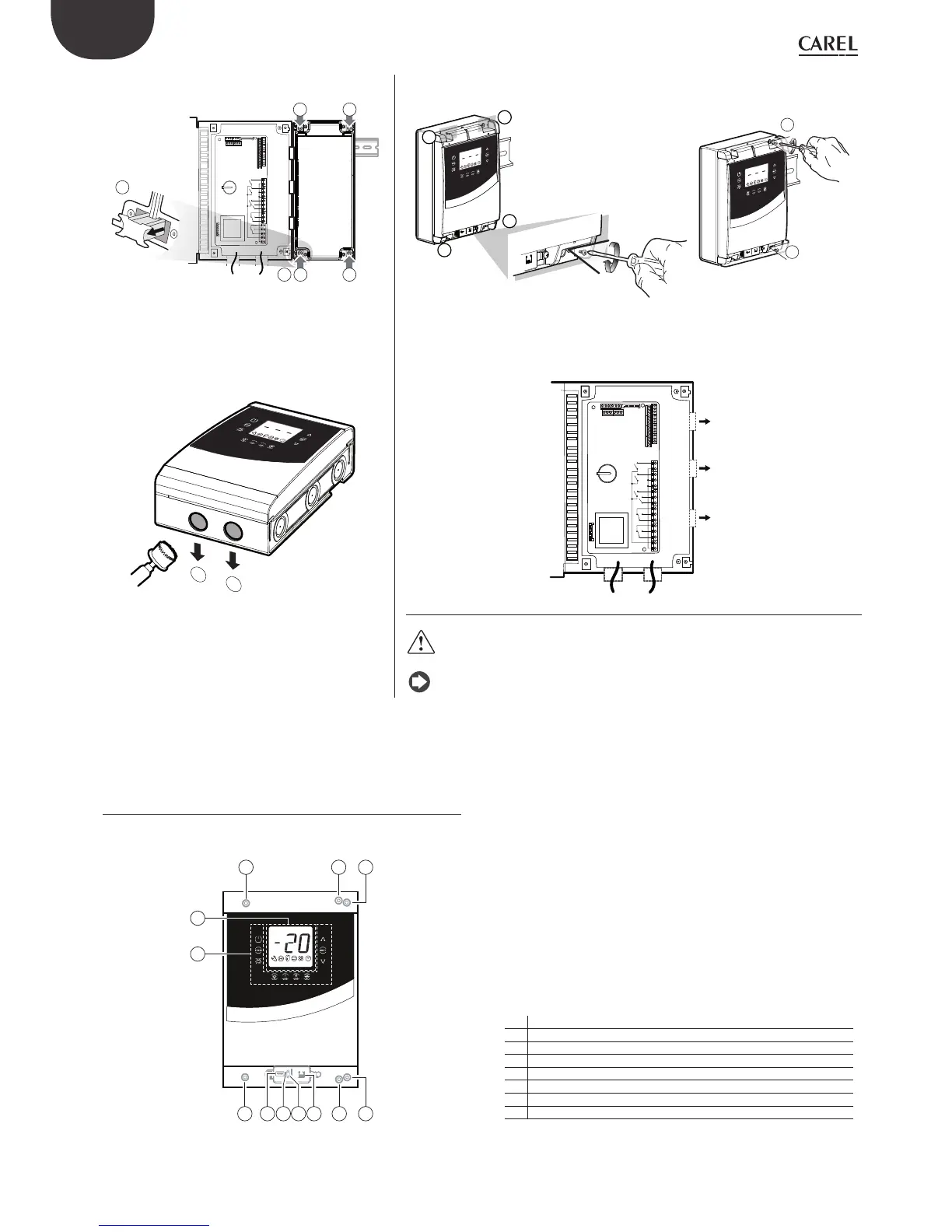
3.a: Mark on the wall the positions of the lower holes,
remove the panel and perform the drills (Ø 4.5 mm); insert
the plugs. Replace the panel on the DIN guide and fi x it
fastening the lower screws.
3.b: Fasten the screws (1) and fi x the panel. Loosen the screws (2) and open the panel.
A
1
2
1
2
N
power supply, compressor
fan, actuators
probes,
digital inputs
connection
to option
modules
4: Use the holes and mount the cable glands to connect:
• on the lower side: supply cables, probes, actuators;
• on the right side: cables for the connection of accessory
modules;
5: Close the panel fastening the screws (2).
Caution: separate the power cables (supply, actuators) from the signal cables
(probes, digital inputs).
Note: use a hole saw to drill the knock-outs (A).
2.2 Structure
Models with single digit display cod. WB000S*
1
2
3 4 3
3 45678 3
Key
1 Keyboard
2 Display
3 Wall mounting holes
4 Locking screws
5 Connector for UltraCella Service (*)
6 Green LED (*)
7 Red LED (*)
8 USB Port (*)
(*) Visible after removing the bottom frame
Fig. 2.c
 Loading...


