18
ENG
UltraCella +0300083EN - rel. 1.5 - 07.02.2015
2.9 Installation
Proceed as follows for installation, making reference to the wiring
diagrams in the previous paragraphs:
1. Connect the supply and probes: the probes can be remote-controlled
up to a maximum distance of 10 metres from the controller as long as
cables with minimum section of 1 mm
2
are used.
2. Program the control: as indicated in chapter “Commissioning” and
“User interface”;
3. Connect the actuators: the actuators should only be connected after
having programmed the controller. It is recommended to carefully
evaluate the maximum capacities of the relays indicated in table
“Technical specifi cations”.
4. Connection to the serial network (if present): all controls are fi tted with a
serial connector for connection to the supervisory network.
Warnings: avoid installing UltraCella control system in environments with
the following characteristics:
• relative humidity over 90% non-condensing;
• strong vibrations or knocks;
• exposure to continuous jets of water;
• exposure to aggressive and polluting atmospheric agents (e.g.: sulphur
and ammonia gases, saline mist, smoke) to avoid corrosion and/or
oxidation;
• high magnetic and/or radio frequency interference (e.g. near
transmitting antennas);
• exposure of the control system to direct sunlight and atmospheric
agents in general.
The following recommendations must be respected when connecting
the controllers:
Warnings:
• incorrect connection of the power supply may seriously damage the
control system;
• use cable ends that are suitable for the terminals. Loosen every screw
and fi t the cable end, next tighten the screws and gently pull the cables
to check their tightness. If using an automatic screwdriver, adjust the
torque to a value less than 0.5 N · m;
• separate as much as possible (by at least 3 cm) the probe signal and
digital input cables from inductive loads and power cables, to avoid
any electromagnetic disturbance. Never lay power cables and probe
cables in the same cable conduits (including those for the electrical
panels). Do not install the probe cables in the immediate vicinity of
power devices (contactors, circuit breakers or other). Reduce the
length of the sensor cables as much as possible, and avoid spirals
around power devices;
• only use IP67 guaranteed probes as end defrost probes; place the
probes with the vertical bulb upwards, so as to facilitate drainage of
any condensate. Remember that the thermistor temperature probes
(NTC) have no polarity, so the order of connection of terminals is not
important.
Caution: in order to ensure the safety of the unit in the event of
serious alarms, all the electromechanical safety devices required
to guarantee correct operation must be fi tted on the unit.
HACCP - CAUTION
When the temperature measurement is relevant for Food Safety (see
HACCP), will be used only temperature probes suggested by Carel. The
standards in force may require the compilation and preservation of
appropriate documentation, as well as periodic checks on instrumentation
and sensors. If in doubt, consult the person in charge of food safety or the
manager of the plant.
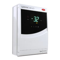
2.10 Connection in supervisoring network
Warnings:
• properly fi x the converter to avoid disconnections;
• perform the wiring without power supply;
• keep the cables of the converter CVSTDUMOR0 separate from power
cables (supply and relay outputs).
The RS485 converter allows you to connect to the UltraCella control
network to the monitoring network for complete control and monitoring
of controls connected. The system provides a maximum of 207 units with
a maximum length of 1000 m. For the connection it is requested the
accessory standard (RS485-USB converter cod. CAREL CVSTDUMOR0) and
a terminating resistor of 120 Ω to be placed on the terminals connected
to the last control. Connect RS485 converter to the controls as shown in
the fi gure. For assigning the serial address see the parameter H0. See the
instruction sheet of the converter for further information.
UltraCella 1
GND
USB-485
Converter
CVSTDUMOR0
120 Ω
T+
T -
GND
T+
T -
USB
UltraCella ...n
to BMS
port
GND
T+
T -
to BMS
port
Fig. 2.s
UltraCella can be connected to both PlantVisor and PlantWatch via BMS
port (RS485 Carel protocol).
Starting from 1.5 release software, both CAREL and Modbus protocols are
available from BMS port, selectable by H7 parameter.
- H7 = 0 CAREL protocol
- H7 = 1 Modbus protocol
Note: To make the change active, switch on and switch off the unit.
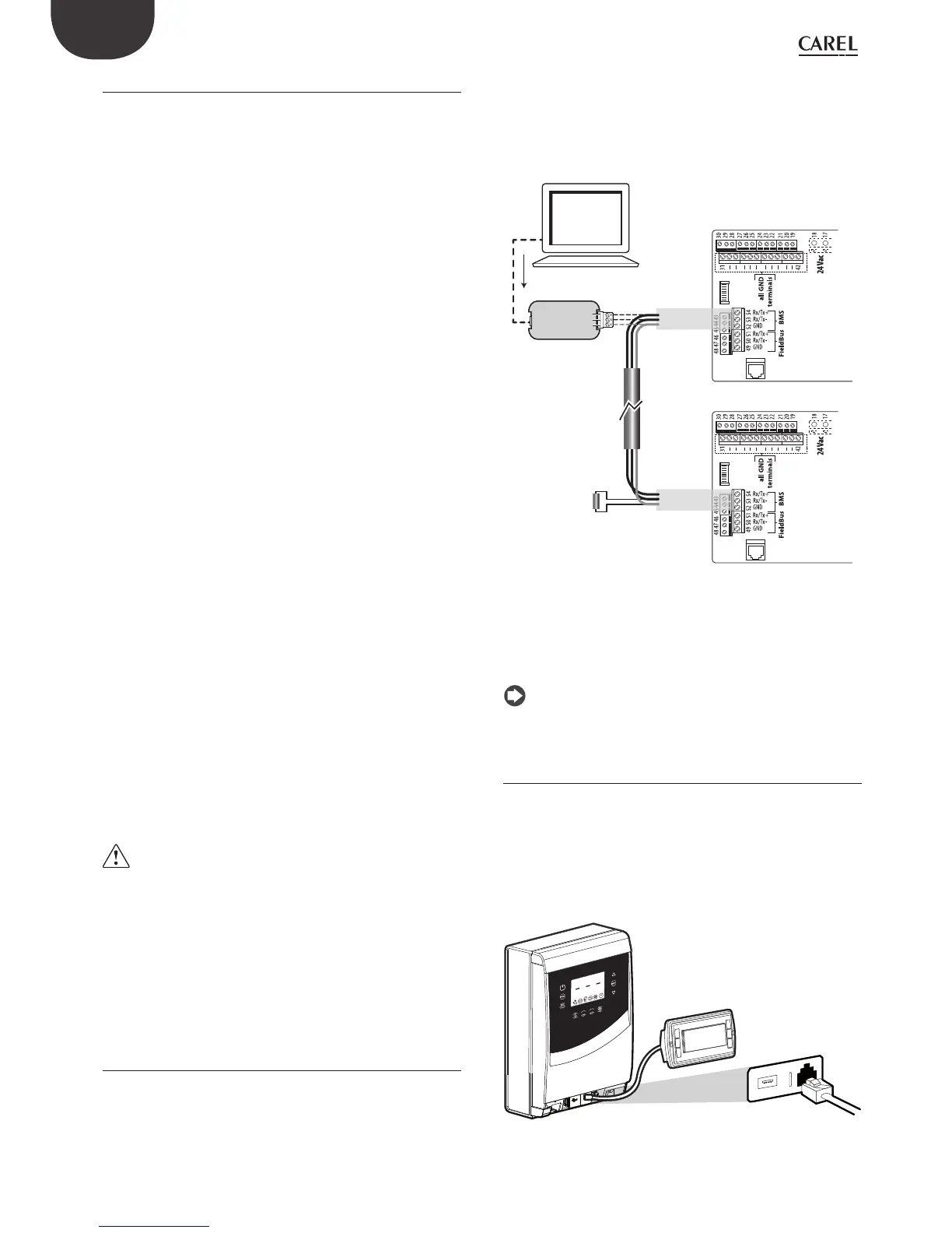
2.11 UltraCella Service terminal
The UltraCella Service Terminal has to be connected via a dedicated
connector, that can be accessed after removing the lower frame
Using the “UltraCella Service Terminal” you can:
• during the fi rst commissioning: insert the fi rst confi guration parameters
following the guided procedure (wizard);
• during normal operation:
1. display the active loads and the main variables: temperature, humidity;
2. perform the control programming, facilitated by contextual help.
1
2
1
2
Fig. 2.t
 Loading...


