14
ENG
UltraCella +0300083EN - rel. 1.5 - 07.02.2015
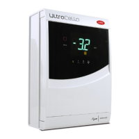
2.5 Ultra EVD module
Mounting with DIN rail
5.a Mark the positions of the bottom holes on the wall (A), remove the
coupling clamps (B), extract the module (C). Drill the corresponding holes
(Ø 4,5 mm) and insert the anchors. Place again the module: mount the
coupling clamps (B) and fasten the screws (A).
G
G0
VBAT
COMA
NOA
1
3
24
Tx/RxGND
DI1
S4
S3
S2
S1
GND
DI2
VREF
N
C
B
PRI 230 V
SEC 24 V
B
B
A A
Fig. 2.i
Mounting without DIN rail
5.b Mark the positions of the 4 holes (A), remove the coupling clamps
(B), extract the module (C). Drill the corresponding holes (Ø 4,5 mm),
depending on drilling template and insert the anchors. Place again the
module: mount the coupling clamps (B) and fasten the screws (A).
G
G0
VBAT
COMA
NOA
1
3
24
Tx/RxGND
DI1
S4
S3
S2
S1
GND
DI2
VREF
N
C
B
PRI 230 V
SEC 24 V
B
B
A A
A A
Fig. 2.j
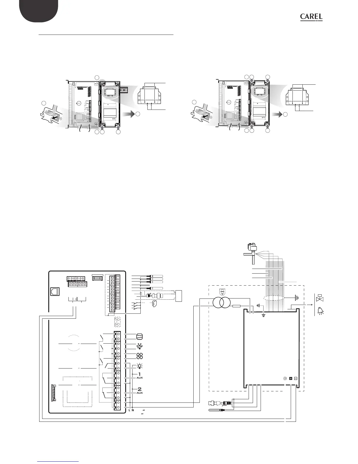
WM00ENNI00: Connect UltraCella to EVD module by serial cable in according with following wiring diagram e refer to below parameters table about EVD
Evo driver commissioning.
WM00ENSI00 and WM00ENS000:
1. Driver commissioning by EVD Evo display.
Connect auxiliary UltraCella output AUX1 or AUX2 relay to digital input DI1 of EVD Evo and set parameters in this way:
• H1=7 (for AUX1) or H5=7 (for AUX2) -> second delayed compressor
• C11=0 -> delay activation second compressor = 0
In this way auxiliary output is set like free contact cooling request, suitable to be connected to digital input DI1 of EVD Evo driver. No setting is requested
in UltraCella.
2. EVD Evo driver commissioning by UltraCella
Connect UltraCella to EVD module by serial cable in according with following wiring diagram e refer to below parameters table about EVD Evo driver
commissioning. If its’ connected by serial cable, driver parameters can be displayed only (not modifi able) by local EVD Evo display.
Once driver is abled by UltraCella (parameter P1=1) its parameters are ones communicated and set by UltraCella, in according with below parameters
table (modifi able by UltraCella only); parameters eventually previously set by EVD Evo display will be lost.
G
G0
VBAT
COMA
NOA
1
3
24
GND Tx/Rx
DI1
S4
S3
S2
S1
GND
DI2
VREF
2 AT
24 Vac
25 VA
shield
NTC
ratiometric pressure
transducer
S
CAREL
ExV
giallo/yellow
bianco/white
verde/green
marrone/brown
FieldBus
24 Vac
BMS
R6
R5
R4
R3
R2
R1
230 V
20 A max
EN60730-1
UL 873
250 V
R5 - R6
12 (10) A
12 A res. 2HP
12FLA 72 LRA
CAREL NTC, PT1000
CAREL NTC, PT1000
CAREL NTC, PT1000
CAREL NTC, analog input 0 to 10 Vdc
B5 analog input
(4 to 20 mA)
OUT
M
+V
0 to 5 Vdc
DI1
(**)
Door switch
B3
B2
B1
48 47 46 45 44 43
49 50 51 52 53 54
VL
GND
GND
Rx/Tx+
Rx/Tx-
GND
Rx/Tx+
Rx/Tx-
GND
Rx/Tx+
Rx/Tx-
GND
Y1
B4
B5
DI1
DI2
DI3
GND
5 VREF
+ Vdc
30
29
28
31
42
27
26
25
21
20
19
18
17
16
15
14
13
12
11
10
9
8
7
6
5
4
3
2
1
24
23
22
analog output (0 to 10 Vdc)
EN60730-1
UL 873
250 V
R3 - R4
10 A res.
5 (3) A
10 A res. 5FLA
18 LRA
EN60730-1
UL 873
250 V
R1 - R2
8 (4) A N.O.
8 A res. 2FLA
12 LRA
CMP
DEF
FA N
LIGHT
UltraCella Control
EVD Module
Fig. 2.k
ULTRACELLA CONTROL ULTRA EVD MODULE BLIND
cod. WM00ENNI00
 Loading...


