16
ENG
UltraCella +0300083EN - rel. 1.5 - 07.02.2015
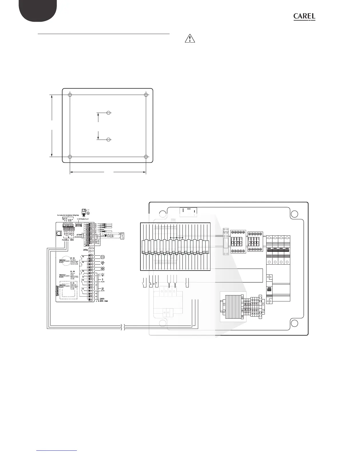
2.7 Ultra 3ph module EVAPORATOR
1. Following drilling template, drill 4 (6) holes on the wall:
• Unscrew 6 fi xing screws of frontal cover
• Remove frontal cover
• Fix panel to the wall by using screws with suitable length to wall
thickness
• Drill side surface of expansion module where it’s necessary and fi t
cable glands to connect: power supply cables, serial cable, probes
and power cables for loads
300
290
160
Fig. 2.o
Important:
• separate the power cable (power supply, actuators) from the signal
cables (probes, digital inputs) and serial cable
• use cable with section suitable to current rating they have to carry
• connect clamp marked with PE to the ground of power supply system
2. Connect three-phase expansion to UltraCella by shielded serial cable
AWG 22
3. Close frontal by screwing the 6 screws
4. Power on UltraCella (230 Vac) and expansion three-phase module
(400 Vac)
5. Activate magnetothermic switch.
QF1
KM2
KM1
QF2
AP1
XP1
XA1
KR3
KR2
Ultra 3PH
I/O module
/O module
CMP
DEF
FAN
LIGHT
to connector board
CAREL NTC, PT1000
CAREL NTC, PT1000
CAREL NTC, PT1000
analog output (0 to 10 Vdc, PWM)
CAREL NTC, analog input 0 to 10 Vdc
B5
analog
input
(4 to 20 mA)
0 to 5Vdc
-
+
GND
GND
Y
109
2727
110
2626
117
1818
118
2020
119
1919
120
2222
128
1616
129
1515
140
2828
141
2929
142
3030
143
2929
146
3131
147
2929
148
2525
149
2424
160
3232
161
3333
162
3434
PE1
17
PE2
PE3
AUX1:1AUX 1
AUX1:2AUX 1
TS1termostato di sicurezza
TS1termostato di sicurezza
SP3Clicson evaporatore
SP3Clicson evaporatore
AP3:LUltraCella
AP3:NUltraCella
ST1defrost
ST1defrost
ST2defrost aux
ST2defrost aux
TS2:Yventilatore evaporatore 0-10 Vdc
TS2:GNDventilatore evaporatore 0-10 Vdc
AUX2:1consenso unita' motocondensante
AUX2:2consenso unita' motocondensante
AP1:J6/-controllo
AP1:J6/+controllo
AP1:J6/GNDcontrollo
Fig. 2.p
 Loading...


