17
ENG
UltraCella +0300083EN - rel. 1.5 - 07.02.2015
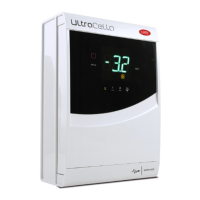
2.8 Ultra 3ph module FULL
1. Following drilling template, drill 4 (6) holes on the wall:
• Unscrew 6 fi xing screws of frontal cover
• Remove frontal cover
• Fix panel to the wall by using screws with suitable length to wall
thickness
• Drill side surface of expansion module where it’s necessary and fi t
cable glands to connect: power supply cables, serial cable, probes
and power cables for loads
300
290
160
Fig. 2.q
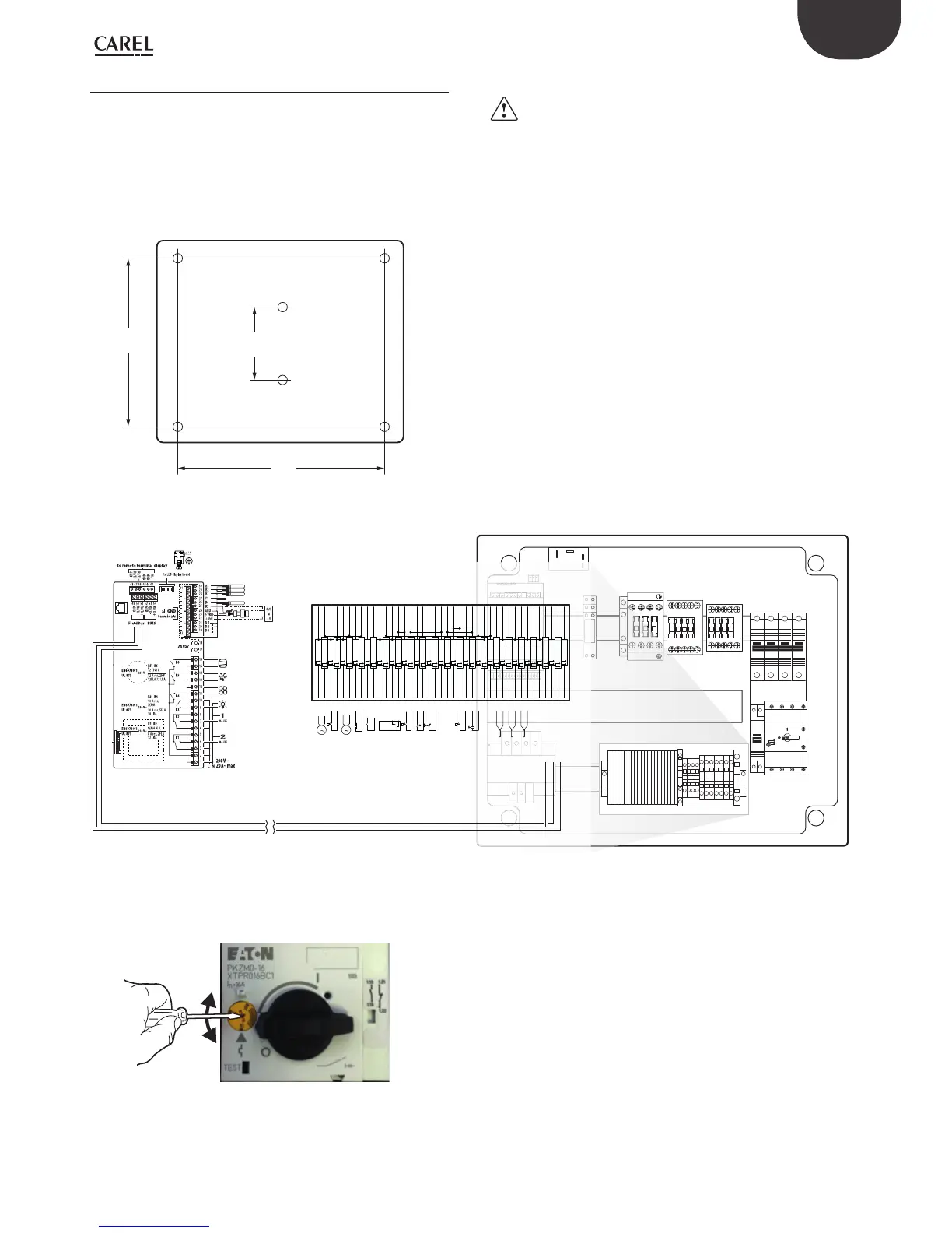
Important:
• separate the power cable (power supply, actuators) from the signal
cables (probes, digital inputs) and serial cable
• use cable with section suitable to current rating they have to carry
• connect clamp marked with PE to the ground of power supply system
• after powering on three-phase expansion check the correct rating
current absorption on the loads
2. Connect three-phase expansion to UltraCella by shielded serial cable
AWG 22
QF1
KM2
KM3
KM1
QF2 QM1
AP1
XP1
XA1
TC1
KR2
Ultra 3PH
I/O module
KR3
63
70
80
90
CMP
DEF
FAN
LIGHT
to connector board
CAREL NTC, PT1000
CAREL NTC, PT1000
CAREL NTC, PT1000
analog output (0 to 10 Vdc, PWM)
CAREL NTC, analog input 0 to 10 Vdc
B5
analog
input
(4 to 20 mA)
0 to 5Vdc
101
19
XA1:103
19
102
18
QF2:N2/XA1:106
18
103
19
XA1:101/KM3:14
19
104
20
XA1:105
20
105
20
XA1:104
20
106
18
XA1:108/XA1:102
18
107
21
KM3:62
21
108
18
XA1:106
18
109
38
KR2:11
38
110
37
KR2:14
37
111
25
FU2:2/XA1:113
25
112
24
KR1:A2/FU1:2
24
113
25
XA1:128/XA1:111
25
114
28
XA1:115
28
115
28
XA1:114
28
116
29
KR1:A1
29
117
27
??:J10/NO1
27
118
31
KM2:A1
31
119
30
??:J10/NO2
30
120
33
KM1:A1
33
121
29
??:J11/C3/4/5
122
32
XA1:126/??:J11/NO3
123
35
124
3535
125
34
KM3:A1
34
126
32
XA1:122
32
127
24
KM3:A2/XA1:129
24
128
25
??:J12/NC6/XA1:113
25
129
24
XA1:127/KR2:A2
24
140
39
??:J2/U1
39
141
40
XA1:143
40
142
41
??:J2/U2
41
143
40
XA1:145/XA1:141
40
144
42
??:J2/U3
42
145
40
??:J2/GND/XA1:143
40
146
45
??:J2/U6
45
147
40
KR1:11
40
160
46
AP:-
46
161
47
AP:+
47
162
48
AP:GND
48
PE109
26
TC1:PE
M
1
M
1
P P P
LN
-
+
GND
GND
Y
condenser fan 1 MV3:1
condenser fan 1 MV3:2
partialization pressure switch condenser fan SP1
partialization pressure switch condenser fan SP1
condenser fan 2 MV4:1
condenser fan 2 MV4:2
crankcase heater RR2
crankcase heater RR2
aux 1 AUX1:1
aux 1 AUX1:2
kriwan AP2:L
kriwan AP2:N
kriwan AP2:11
kriwan AP2:14
pressure switch SP2
pressure switch SP2
security thermostat TS1
security thermostat TS1
evaporator clicson SP3
evaporator clicson SP3
pump down TK1
pump down TK1
liquid valve YV1
liquid valve YV1
ultracella ULTRACELLA:L
ultracella ULTRACELLA:N
defrost ST1
defrost ST1
defrost aux ST2
defrost aux ST2
temp condensatore ST3
temp condensatore ST3
fan evaporatore 0-10vdc 7AP1:Y
fan evaporatore 0-10vdc 7AP1:GND
controller AP1:J6/-
controller AP1:J6/+
controller AP1:J6/GND
Fig. 2.r
3. Close frontal by screwing the 6 screws
4. At the fi rst start-up of the unit, it’s suggested to calibrate motor circuit
breaker on eff ective compressor absorption rating
5. Power on UltraCella (230Vac) and expansion three-phase module
(400Vac)
6. Activate magnetothermic switch and motor circuit breaker
 Loading...


