31
ENG
UltraCella +0300083EN - rel. 1.5 - 07.02.2015
4. COMMISSIONING
4.1 First commissioning
After wiring the electrical connections and the power supply (see
installation chapter), the operations required for commissioning the
UltraCella control system depend on the type of interface used. Refer to
some parameters such as:
1. Set-point and diff erential;
2. Probes and digital inputs confi guration;
3. Selection of the type of defrost and fans operation;
4. Cold room light management.
Types of interfaces:
• board with LED display: parameters confi guration is performed using
the display and the keyboard based on the procedure described in
chap.3 “parameters change”. Alternatively, you can connect the remote
graphic terminal “UltraCella Sevice Terminal” and enter the wizard
menu for fi rst commissioning (wizard);
• USB memory key: put the control on OFF and load the programming
parameters from USB memory key (uPd command, UPLOAD, see
Chapter 3);
• supervisor: in order to facilitate the launch of a large number of controls
UltraCella using only the supervisor you can limit the operation of the
fi rst commissioning to the serial address setting. The confi guration is
postponed to a later time using the supervisor.
After the confi guration you can enable the control of the cold room by
pressing the ON/OFF key.
4.2 Parameters to be set for the
commissioning
Par Description Categ. Def Min Max U.M.
St Set point CtL 0 r1 r2 °C/°F
rd Diff erential CtL 2.0 0.1 20 °C/°F
/P Type B1 to B3 Pro 0 0 2 -
/A2 B2 confi guration Pro 0 0 2 -
/A3 B3 confi guration Pro 0 0 3 -
/P4 Type B4 Pro 0 0 2 -
/A4 B4 confi guration Pro 0 0 3 -
/P5 Type B5 Pro 0 0 0 -
/A5 B5 confi guration Pro 0 0 1 -
A5 Digital input confi guration 2 (DI2) ALM 0 0 14 -
A9 Digital input confi guration 3 (DI3) ALM 0 0 14 -
d0 Type of defrost dEF 0 0 3
dt1 End defrost temperature, main
evaporator
dEF 4.0 -50.0 200.0 °C/°F
dt2 End defrost temperature, auxiliary
evaporator
dEF 4.0 -50.0 200.0 °C/°F
dP1 Maximum defrost duration dEF 30 1 250 min
dd Dripping time after defrost (fans
off )
dEF 2 0 30 min
Fd Post dripping time (fans off ) Fan 1 0 30 min
F3 Evaporator fan during defrost
0/1=on/off
Fan 1 0 1 -
C12 Compressor safety for door switch
0 = disable door management
doL 5 0 5 min
d8d Compressor restart time for door
switch
doL 0 0 240 min
A3 Disable door microswitch
0=enabled
1=disabled
doL 0 0 1 -
tLi Light on with door open doL 120 0 240 min
A4 Light management
0 = door switch + light key
1 = light key
doL 0 0 1 -
c1 Minimum time between
compressor starts
CmP 6 0 15 min
c2 Minimum compressor off time CmP 3 0 15 min
c3 Minimum compressor on time CmP 3 0 15 min
Tab. 4.a
4.3 Single digit display models cod.
WB000S* commissioning
UltraCella with single row display
Fig. 4.a
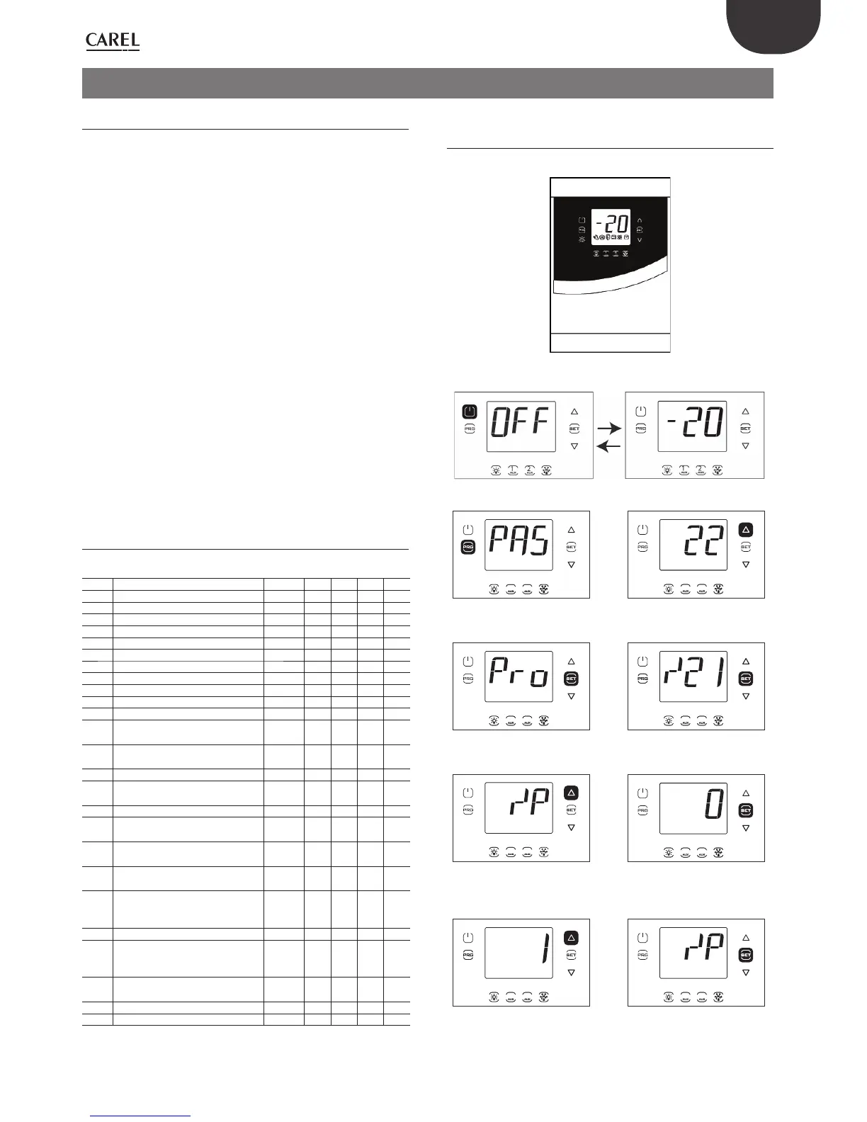
1. First switch the controller OFF (press ON/OFF).
1 21 2
1 21 2
2. Press Prg for 2 sec: the password
prompt is displayed (PAS).
3. Press UP and enter the
password: 22.
1 21 2 1 21 2
4. Press Set: the fi rst category is
displayed: Pro (Probes).
5. Press Set: the fi rst parameter is
displayed: /21.
1 21 2
1 21 2
6. Press repeatedly UP to reach
the parameter /P.
7. Press Set to set the value of the
parameter (see settings in the
parameter table).
1 21 2 1 21 2
8. Press UP to modify the value. 9. Press Set to confi rm and return
to the parameter code. The new
value has now been saved on the
controller.
 Loading...


