45
ENG
UltraCella +0300083EN - rel. 1.5 - 07.02.2015
6.6 Continuous cycle
To activate the continuous cycle by keyboard see Chapter 3 (parameter
value cc> 0). During operation in a continuous cycle, the compressor
continues to operate regardless the control, for the time “cc”, to lower the
temperature even below the set point. The continuous cycle is stopped
after the time cc or when reaching the minimum specifi ed temperature,
corresponding to the minimum temperature alarm threshold (AL). If,
after the end of the continuous cycle, the temperature falls below the
minimum temperature threshold, the low temperature alarm signal can
be ignored by suitably setting the c6 parameter: the alarm bypass delay
time after continuous cycle.
Par. Description Def Min Max U.M.
cc Continuous cycle duration 0 0 15 hour
c6 Low temperature alarm delay after
continuous cycle
2 0 250 hour
A5 Digital input confi guration 2 (DI2)
…
14 = Continuous cycle activation
0 0 14 -
A9 Digital input confi guration 3 (DI3)
…
14 = Continuous cycle activation
0 0 14 -
6.7 Door switch control
See chap. 4
6.8 Defrost
Introduction
These parameters (dd1…dd8) can be used to set up to 8 defrost events
linked to the system clock (RTC)
Par. Description Def Min Max U.M.
dd1…8 Defrost 1…8: day
0 Disabled
1…7 Monday…Sunday
8 From Monday to Friday
9 From Monday to Saturday
10 Saturday and Sunday
11 Daily
0 0 11 -
hh1…8 Defrost 1…8: hour 0 0 23 hour
nn1…8 Defrost 1…8: minute 0 0 59 min.
UltraCella allows you to manage the following types of defrost, depending
on parameter d0:
0. electric heater defrost by temperature (placed near the evaporator);
1. hot gas defrost by temperature.
2. electric heater defrost by time;
3. hot gas defrost by time.
Note: Ed1 and Ed2 indicate that the defrost ended due to time-
out.
The end of the defrost cycle can be by temperature, and in this case it is
necessary to install the defrost probe Sd (to select between B2 and B3) or
by time. In the fi rst case the defrost ends if the probe Sd measures a value
greater than the value of dt1 or dP1 time has elapsed, in the second case
if the defrosting phase exceeds the maximum time dP1. At the end of
the defrost the controller can enter in dripping status (present if dd> 0),
in which the compressor and the fans are turned off , and subsequently in
the state of post-dripping (if present Fd> 0), in which the control resumes
with fans off . You can choose the display on the user terminal during
defrost, using parameter d6.
Par. Description Def Min Max U.M.
d0 Type of defrost
0 Heater by temperature
1 Hot gas by temperature
2 Heater by time
3 Hot gas by time
003-
dt1 End defrost temperature, main
evaporator
4 -50 200 °C/°F
dt2 End defrost temperature, auxiliary
evaporator
4 -50 200 °C/°F
dP1 Maximum defrost duration 30 1 250 min
dP2 Maximum defrost duration, auxiliary
evaporator
30 1 250 min
d6 Terminal display during defrost
0 = Temperature alternated with dEF
1 = Last temperature shown before
defrost
2 = dEF
102-
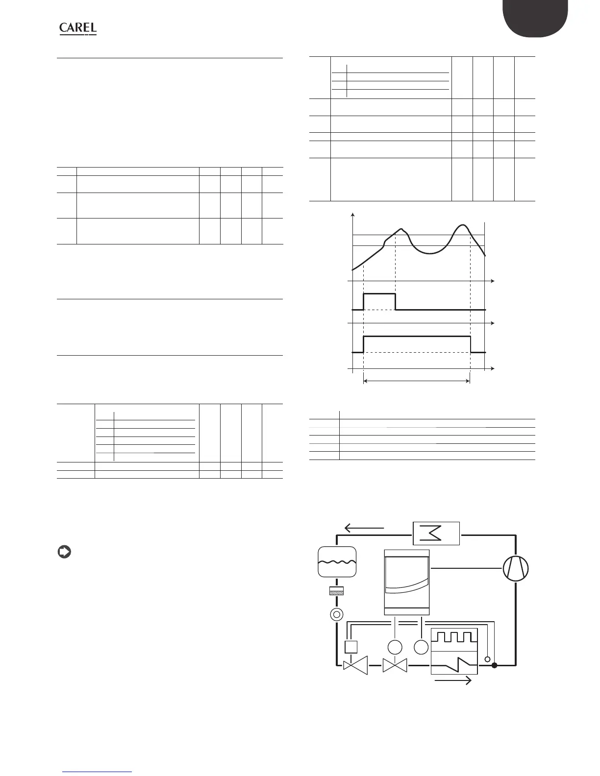
Sd
DEF
DEF
t
t
t
OFF
d0=2, 3
d0=0, 1
ON
OFF
ON
dt1
dt1-1
dP1
Fig. 6.h
Key
t Time
dt1 End of defrost temperature
dP1 Maximum defrost duration
Sd Defrost Probe
d0 Type of defrost
DEF Defrost
1. electric heater defrost (d0 = 0, 2): operating cycle.
The operating cycle refers to default values of the parameters F2 and F3.
T
M B3
E
S
F
L
C
CMP
V2
PDV
Fig. 6.i
 Loading...


