63
ENG
UltraCella +0300083EN - rel. 1.5 - 07.02.2015
9. TECHNICAL SPECIFICATIONS
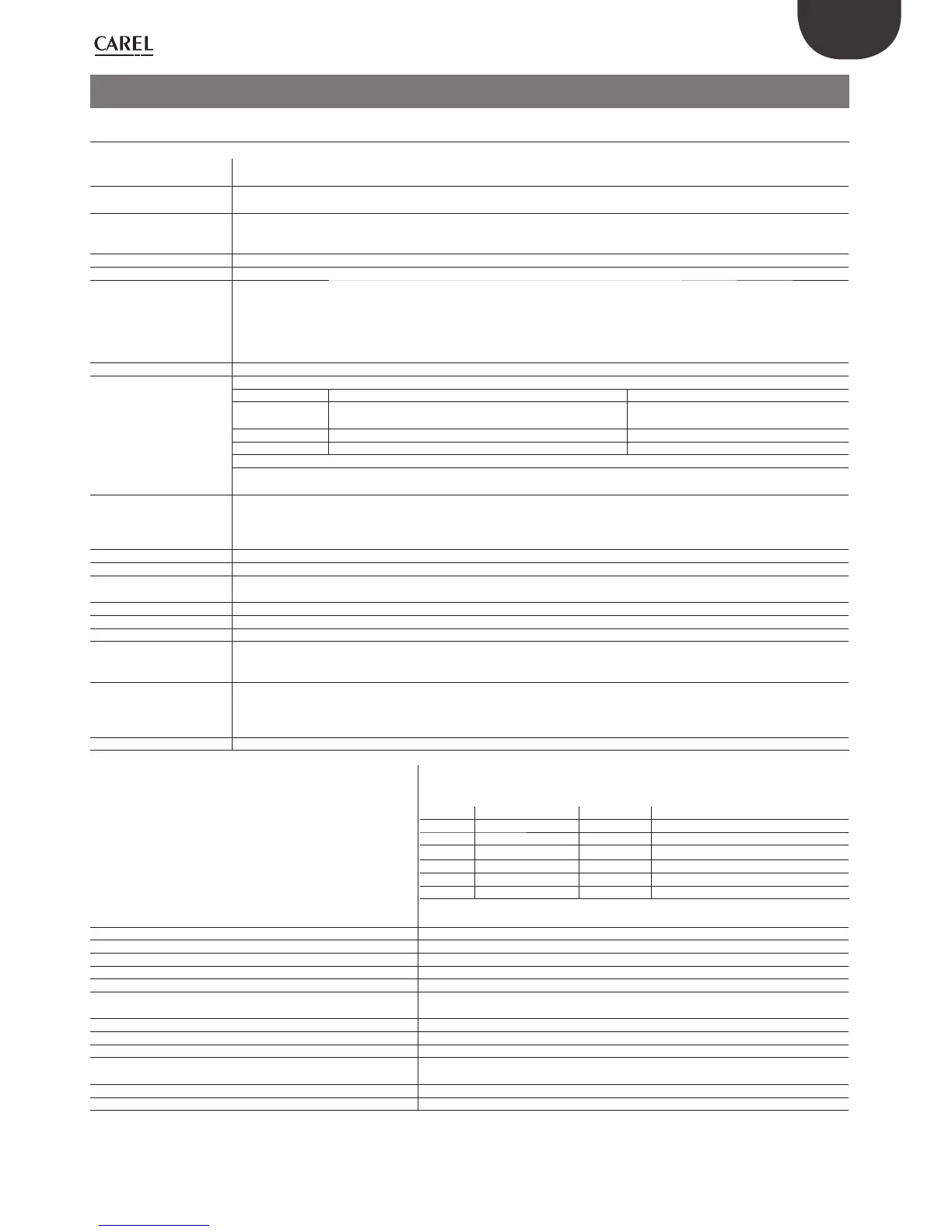
9.1 UltraCella technical characteristics
Power Supply Model 230V: Voltage 230 V~ (+10/-15%), 50/60 Hz; Power 18 VA, 100 mA~ max.
Model 24V: Voltage 24 V~ (+10/-15%), 50/60 Hz; Power 18 VA, 1A~ max.
Insulation ensured
by 230V power supply
Insulation for low voltage: reinforced, 6 mm in air, 8 mm superfi cial, 3750 V.
Insulation for relay outputs: reinforced, 3 mm in air, 4 mm superfi cial, 1250 V.
Analog inputs B1, B2, B3: NTC, PT1000 (+-3%)
B4: NTC, 0...10Vdc (+-3%)
B5: 0...5Vdc ratiometric (+-3%) , 4...20mA (+-3%)
Analog output Y1: 0...10 Vdc (10mA max,+-5%)
Note: When installing, keep the supply and loads connections away from the cables of the probes, digital inputs, and monitoring device.
Probe Type NTC std. CAREL: 10 kΩ at 25°C, range from -50°C to 90°C;
measuring error: 1°C in range from -50°C to +50°C; 3°C in range from +50°C to +90°C
NTC HT: 50 kΩ at 25°C, range from 0°C to 150°C;
measuring error: 1.5°C in range from 0°C to +115°C; 4°C in range from +115°C to +150°C
PT1000 std. CAREL: 1000 Ω at 0°C, range from –50°C to +90°C;
measuring error 3°C in range from –50°C to 0°C; 5°C in range from 0°C to +90°C
Probe power supply +Vdc 12 V+-30%, 25 mA max; 5VREF: 5V+-2%
Relay output Applicable ratings based on the relay type
Type of Relay EN60730 -1 (250 V ~) UL 873 (250 V ~)
8A (AUX1, AUX2) 8 (4)A on N.O.; 6 (4)A on N.C.; 2 (2)A on N.C. and N.O. (100000
cycles)
8A resistive 2FLA 12LRA, C300 (30000 cycles)
16A,(LIGHT, FAN) 10A resistive, 5 (3)A (100000 cycles) 10A resistive, 5FLA 18LRA (30000 cycles)
30A(COMP, DEF) 12 (10)A (100000 cycles) 12A resistive, 2HP, 12FLA 72LRA (30000 cycles)
NOTE: The sum of the loads currents COMP, DEF, FAN accessed at the same time should not exceed 20A
Insulation for low voltage: reinforced, 6 mm in air, 8 superfi cial, 3750 V.
Insulation between independent relay outputs: reinforced, 3 mm in air, 4 superfi cial, 1250 V.
Connections Section of conductors for analog inputs and outputs, digital inputs, serial: from 0.5 to 2.5mm2 (from 20 to 13 AWG);
Section of supply and loads cables: from 1.5 to 2.5 mm2 (from 15 to 13 AWG)
Serial connections:use shielded cables
Maximum length of the cables: 10 m
Container Plastic: sizes 200 x 100 X 190 mm
Assembly On wall (with plastic container): using fastening screws for front board
Display LED display: 3 and 4 digits, display from -99 to 999; operating status indicated by LEDs and icons formed on the polycarbonate
applied to the plastic
Keyboard 10 keys on keyboard in polycarbonate membrane applied to the plastic
Clock with buff er battery Available depending on the model
Buzzer Available on all models.
Clock Depending on the model installed.
Accuracy: ±100 ppm
Battery: “button” type with lithium code CR2430 voltage: 3Vdc (sizes 24x3 mm)
Serial 3 types of available serials: pLAN, BMS, Fieldbus
PLAN : Driver HW RS485, telephone jack (available only on few models) and screw terminals
BMS Driver HW RS485, screw terminals
Fieldbus: Driver HW RS485, screw terminals
USB Type: Host (A connector); 5Vdc supply, maximum absorption: 100mA (low power devices)
Operating conditions Only board: -10T65°C; <90% U.R. non condensing
With plastic container: -10T50°C, <90% U.R. non condensing
Relay identifi cation, type and maximum resistive current to operating temperature:
Relay Associated load Type of Relay Max resistive current applicable
R1 (AUX2) 8A 8A
R2 (AUX1) 8A 8A
R3 (LIGHT) 16A 10A
R4 (FAN) 16A 10A
R5 (DEF) 30A 12A
R6 (COMP) 30A 12A
NOTE: The sum of the loads currents COMP, DEF, FAN accessed at the same time should not
exceed 20A.
Storage conditions -20T70°C, < 90% U.R. non condensing
Front protection rating With plastic container: IP65
Environmental pollution 2, normal situation
PTI of the isolating materials Printed circuits 250, plastic and insulation materials 175
Resistance to fi re class: Category D
Protection against overcharging class Category II, without PE terminal
Category I, with PE terminal
Type of action and disconnection Relay contact 1 B (micro-disconnection)
Control system manufacture Incorporated, electronic control device
Classifi cation according to protection against electric shock Class II by means of appropriate incorporation
Device intended to be hand-held or built into equipment
designed to be hand held
No
Class and structure of the software Class A
Control front cleaning Only use neutral detergents and water
Tab. 9.a
 Loading...


