9
ENG
UltraCella +0300083EN - rel. 1.5 - 07.02.2015
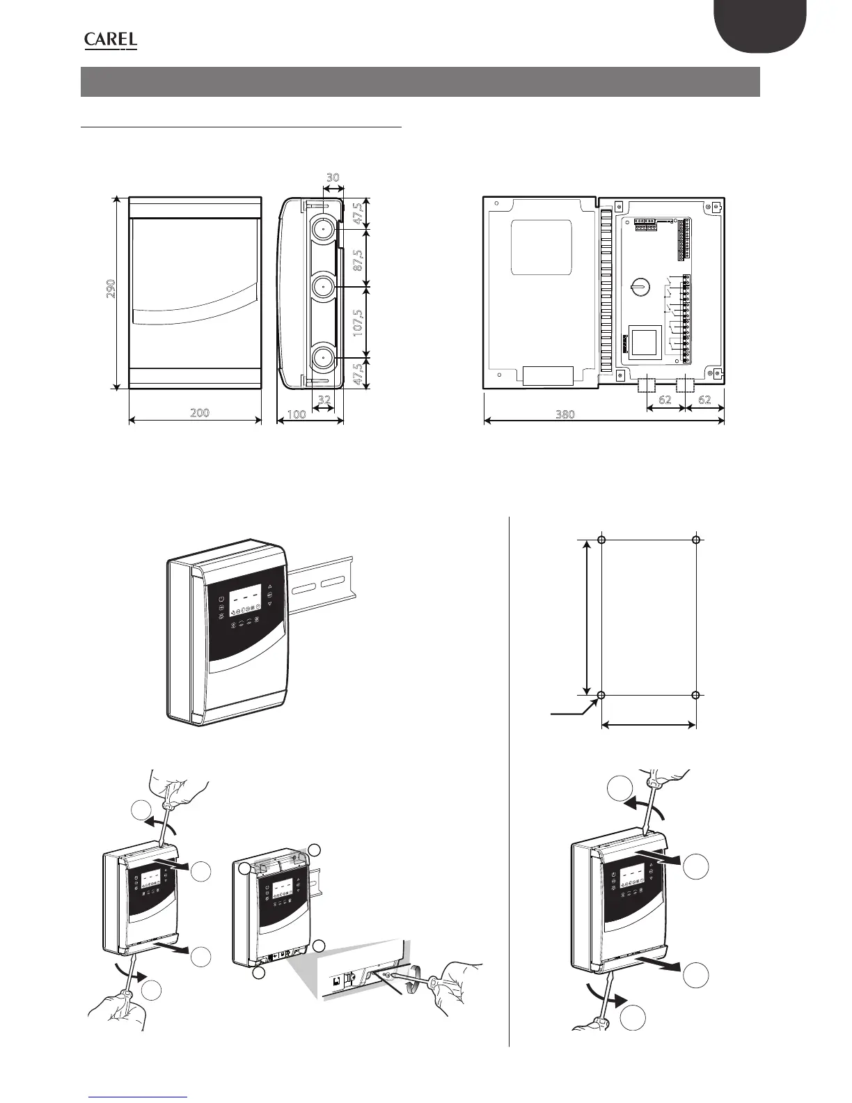
2. INSTALLATION
2.1 Assembly and sizes (mm)
The control system has holes on the lower and right side, in which the
installer can insert the cable glands.
200
290
87,5
107,5
47,5
47,5
30
32
100
N
62 62
380
Fig. 2.a Fig. 2.b
Mounting
A: with DIN rail B: without DIN rail
1
2
1
2
260
156
Ø 4,5
1.a: Fix the DIN rail and insert the controller 1.b: Make 4 holes (Ø 4,5 mm) according to the drilling
template and insert the dowels (mm)
2
2
1
2
1
2
1
1
1
1
1
1
1
2
1
2
2
2
1
2
1
2
1
1
2.a: Remove the frames, loosen the screws (1) and open the panel 2.b: Remove the frames

 Loading...


