48
ENG
UltraCella +0300083EN - rel. 1.5 - 07.02.2015
Par. Description Def Min Max U.M.
F5 Evaporator fans cut-off temperature
(hysteresis 1°C)
15 -50 50 °C/°F
F6 Maximum fans speed 100 F7 100 %
F7 Minimum fans speed 0 0 F6 %
To enable the algorithm, it’s necessary to select variable speed fans mode
(F0=2) and set analogue output 0…10 Vdc (HO1=2).
Par. Description Def Min Max U.M.
F0 Evaporator fans management
…
2 = variable speed fans
002-
HO1 Output Y1 0…10 V confi guration
…
2 = variable speed fans regulated on Sd
002-
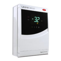
t
t
Sd
F0 = 2
F5+1
F5
F1
F1-Frd
F6
FAN
F7
0%
Fig. 6.o
Evaporator Fan (analog output) F0= 2
Key
Sd Evaporator probe
F0 Evaporator fans management
F1 Fan start temperature
Frd Fan activation diff erential
Note:
• if two evaporator probes are confi gured (Sd1 and Sd2), speed fans is
calculated in relation to probe which is measuring higher temperature
(to limit hot air fl ow):
if Sd1>Sd2 –› regulation on Sd1;
if Sd1<Sd2 –› regulation on Sd2.
In case of defrost probe failure, speed fans is fi xed to maximum value
defi ned by parameter F6.
• If F0=2 and HO1=2, speed fan is calculated in according to Figure 6.o.
Anyway, if speed fan is higher than 0, “FAN” relay DO3 is ON anyhow
(closed):
if speed fan (Y1) > 0V –› “FAN” relay ON (DO3 closed)
if speed fan (Y1) = 0V –› “FAN” relay OFF (DO3 open)
• If F0=0,1 (fi xed speed fans by “FAN” relay DO3), analogue output is set
to 0 (Y1=0V)
• Inside modulation interval (F1-Frd < Sd < F1), speed fan is modulated
in proportional way (e.g. Sd=F1-Frd/2 –› Y1 correspond to (F6+F7)/2
percentage)
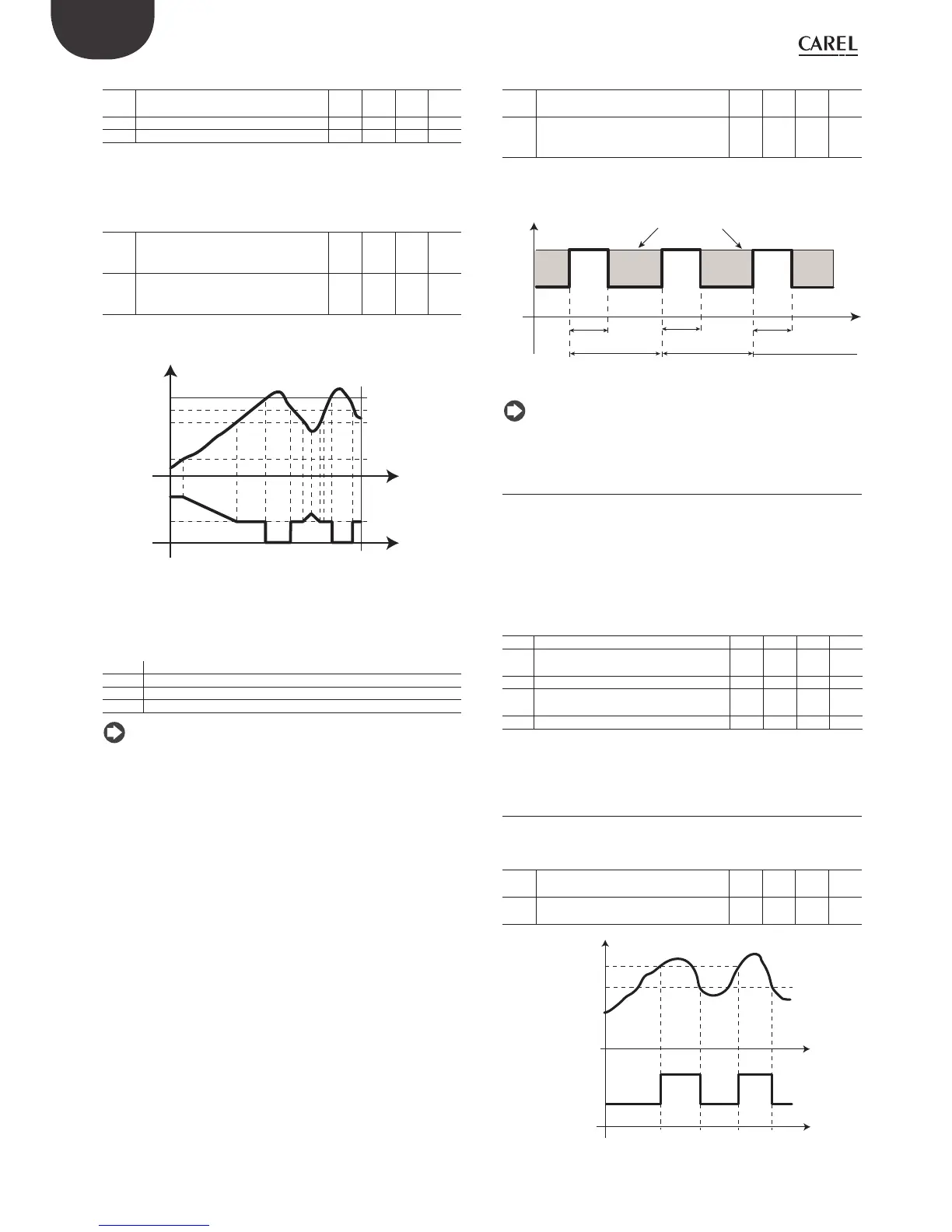
Because of mechanical inertia of motor, some EC fans cannot start with
a low speed set by parameter F7. To overcome this, fans can be started
with maximum speed set by parameter F7 for a “peak time” defi ned by
parameter F8, irrespectively of Sd temperature.
On the other hand, if fans operates for too long time at a reduced speed,
ice can form on the blades. To avoid this, at interval of F10 minutes, fans
are forced to maximum speed for “peak time” defi ned by F8
Par. Description Def Min Max U.M.
F8 Fans peak time
0 = function disabled
0 0 240 s
F10 Evaporator fans forcing time at
maximum speed
0 = function disabled
0 0 240 min
t
speed fans dened by Sd
F7
F6
F8
F8
F8
F10
F10
Note: Cyclic time at maximum speed (determined by both F8 and
F10) is not allowed when door is open.
6.9.3 Evaporator fans during defrost
There is the possibility to force the start of the evaporator fans during
control (parameter F2) and during defrost (parameter F3). During
the dripping periods (parameter dd > 0) and post-dripping periods
(parameter Fd > 0) the evaporator fans are always off . This is useful to
allow the evaporator to return to normal temperature after defrosting,
thus avoiding forcing hot air on evaporator. dd is used to force the stop
of the compressor and the evaporator fan after a defrost cycle in order to
facilitate evaporator dripping.
Par. Description Def Min Max U.M.
F2 Fan activation time with CMP off 30 0 60 min
F3 Evaporator fans during defrost
0/1=on/off
101-
Fd Post dripping time (fans off ) 1 0 30 min
F4 Humidity output during defrost
0/1 = ON/OFF
101-
dd Dripping time after defrost (fans off ) 2 0 30 min
6.10 Condenser fans
The condenser fans are activated based on parameters FC4 and A0, after
confi guring the digital output AUX.
Par. Description Def Min Max U.M.
FC4 Condenser fan deactivation
temperature
40 -50 200 °C/°F
A0 Alarm and fan diff erential 2.0 0.1 20 °C/°F
FAN
OFF
ON
FC4
FC4+A0
Sc
t
t
Fig. 6.p
 Loading...


