43
ENG
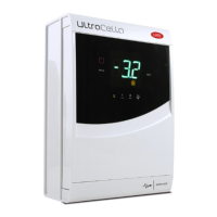
UltraCella +0300083EN - rel. 1.5 - 07.02.2015
6. CONTROL
6.1 Switching the controller ON and OFF
The state of ON/OFF can be controlled by more than one source, keyboard,
digital input and supervisor. When the controller is off , the display will
show the temperature selected for parameter /t1 alternating with the
OFF message. The digital input can be used to switch the controller on/
off , setting parameter A5/A9 to “6”. The activation state of ON / OFF from
digital input has priority over the one from the supervisor and keyboard.
Origin Priority Notes
Digital input 1 Disable On/Off from keypad and supervisor
Keyboard 2
Supervisor 3
Tab. 6.a
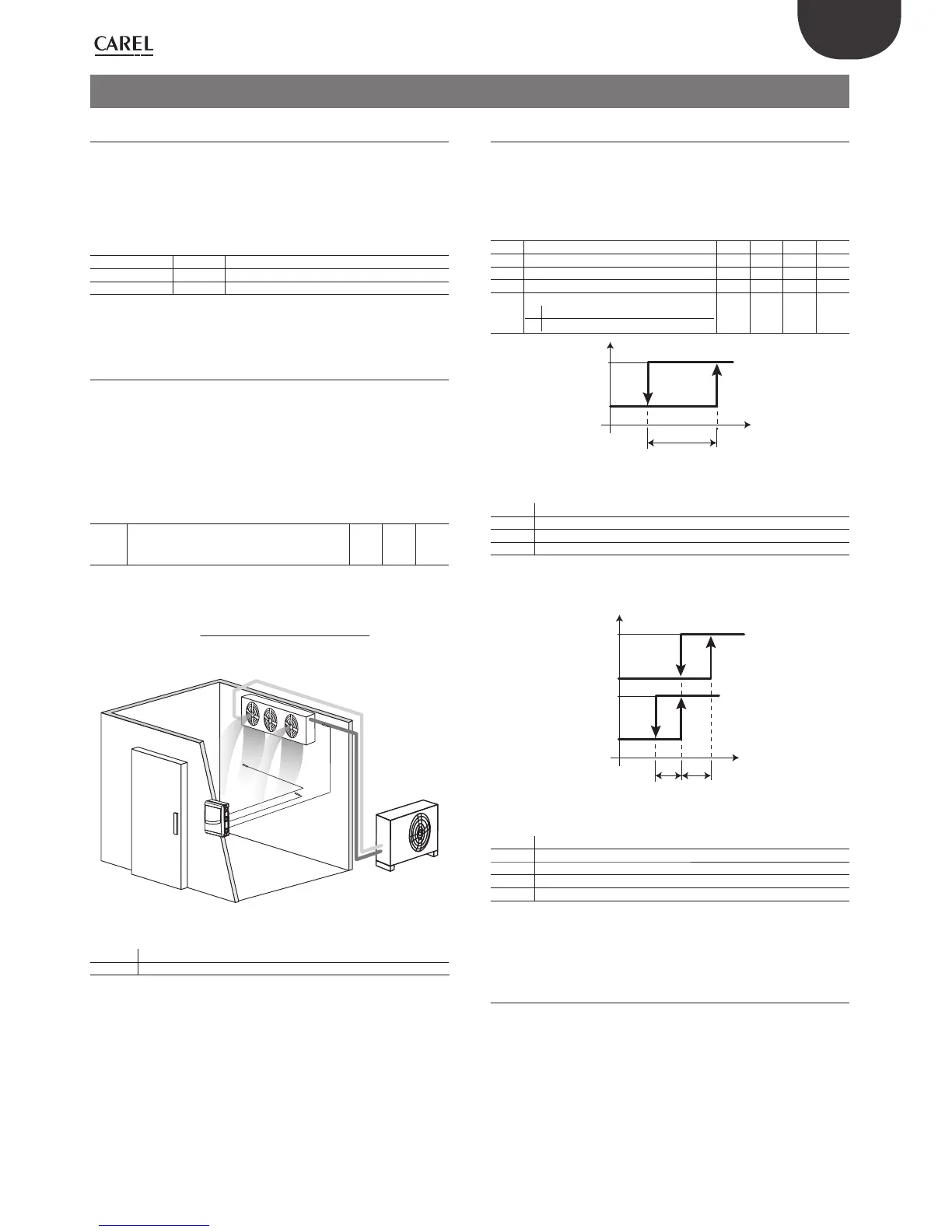
6.2 Virtual probe
The control output of the controller is the compressor output. The control
probe is the ambient probe B1 (default setting), while the probes B2, B3,
B4, B5 may be associated with the functions of defrost probe 1/2, outlet
probe, intake probe, condenser probe. If the cold room is very large you
should also use a second probe to control the temperature of the room.
The controller will activate the compressor based on the requirements
of the virtual probe (Sv), obtained from weighed average of the 2 probes
(B1, B2).
Par. Description Def Min Max U.M.
/4 Virtual probe composition
0 = probe B1
100 = probe B2
0 0 100 -
The /4 parameter is used to determine the virtual probe (Sv) as a weighted
average of the control sensor probe B1 and B2, according to the formula:
Sv=
[(B1*(100-/4)+B2*/4]
100
UltraCella
Fig. 6.a
Key
B1 Outlet probe
B2 Intake probe
6.3 Set point
The reference output is the compressor (CMP).
The controller can operate in two diff erent modes, that can be selected
using parameter r3:
• direct with defrost;
• direct without defrost;
Par. Description Def Min Max U.M.
St Set point 0 r1 r2 °C/°F
rd Diff erential 2.0 0.1 20 °C/°F
r1 Minimum set point -50 -50 r2 °C/°F
r2 Maximum set point 60 r1 200 °C/°F
r3 Operating mode
0 Direct with defrost
1 Direct without defrost
001-
Sv
CMP
St
rd
OFF
ON
Fig. 6.b
Key
St Set point
rd Diff erential
Sv Virtual probe
CMP Compressor
If you have activated the second compressor output (H1, H5 = 13, 14) on
AUX output, the activation of the compressor is at St + rd/2 and that of
the auxiliary compressor AUX in St + rd, according to the fi gure below.
Sv
CMP
AUX
St
rd/2 rd/2
rd
OFF
ON
OFF
ON
Fig. 6.c
Key
St Set point
rd Diff erential
Sv Virtual probe
CMP Compressor
AUX Auxiliary output
6.4 Pump down
The pump down has the aim to completely empty the evaporator of the
refrigerant at each stop of the compressor. After this phase, you can safely
turn off the compressor, so that the liquid is not present the next time the
compressor is started. When the set point is reached, the control closes
the pump down valve to stop the fl ow of refrigerant to the evaporator,
and, after a certain time, the compressor. In the application diagram
there are the pump down valve and the low pressure switch. When the
control requires turning on the compressor, if the safety periods c1 and
c2 have passed, the pump down valve is opened and after the time set in
parameter c8 the compressor is activated.
 Loading...


