11
ENG
UltraCella +0300083EN - rel. 1.5 - 07.02.2015
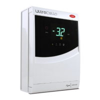
Models with double digit display cod. WB000D*
1
2
3 4 3
3 45678 3
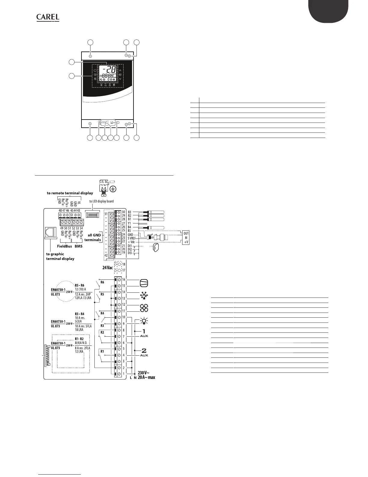
Key
1 Keyboard
2 Display
3 Wall mounting holes
4 Locking screws
5 Connector for UltraCella Service (*)
6 Green LED (*)
7 Red LED (*)
8 USB port (*)
(*) Visible after removing the bottom frame
Fig. 2.d
2.3 Wiring diagram
CMP
DEF
FAN
LIGHT
to connector board
CAREL NTC, PT1000
CAREL NTC, PT1000
CAREL NTC, PT1000
analog output (0 to 10 Vdc)
CAREL NTC, analog input 0 to 10 Vdc
B5
analog
input
(4 to 20 mA)
0 to 5Vdc
DI1
Door switch
Key
B1…B5 Analogue inputs 1…5
DI1 Door switch
DI2, DI3 Digital inputs 2, 3
Y1 0…10 V analogue output
GND Grounding for signals
5 VREF Ratiometric pressure probe power supply
+Vdc Active probe supply (humidity)
CMP DO1 (*) Compressor
DEF DO2 (*) Defrost
FAN DO3 (*) Evaporator fan
LIGHT DO4 (*) Light
AUX1 DO5 (*) Auxiliary output 1
AUX2 DO6 (*) Auxiliary output 2
L, N Power Supply
Fieldbus Fieldbus Serial
BMS BMS Serial
Tab. 3.a
(*) Digital outputs display in the multifunction module (see chap.
3).
Fig. 2.e
 Loading...


