34
ENG
UltraCella +0300083EN - rel. 1.5 - 07.02.2015
4.6.2 Probes confi guration
The UltraCella controls have a maximum of 5 analog inputs, of which
3 can be confi gured as temperature probes (NTC probes, NTC high
temperature probes, PT1000), the fourth as temperature probe or input 0
... 10 V, the fi fth can be confi gured as input 4 ... 20 mA.
Analogue Inputs Type
B1
B2
B3
NTC10 kΩ a 25°C, range -50T90°C,
NTC extended range, NTC50 kΩ a 25°C, range 0T150°C;
PT1000, 1000 Ω a 0°C, range -50T90°C
B4 NTC10 kΩ a 25°C, range -50T90°C,
NTC extended range, NTC50 kΩ a 25°C, range 0T150°C
0…10 V
B5 4…20 mA
Tab. 4.b
Below the parameters with the selection:
Par. Description Def Min Max U.M.
/P Type B1 to B3
0 = NTC Standard Range -50T90°C
1 = NTC Enhanced Range 0T150°C
2 = PT1000
002-
/P4 Type B4
0 = NTC Standard Range -50T90°C
1 = NTC Enhanced Range 0T150°C
2 = 0 to 10 V
002-
/P5 Type B5
0 = 4 to 20 mA
000-
4.6.3 Probes function assignment B1, B2, B3, B4, B5
The control, inside the cold room, can use the probes:
• outlet;
• intake;
• defrost, placed in the evaporator, preferably where the ice resides most;
• condenser, used to protect the compressor due to high discharge
temperature, associated with fowling of the condenser or fan failure.
Probe B1 is confi gured as environment probe and its function cannot be
changed.
Par. Description Def Min Max U.M.
/A2 Confi guration B2
0 Absent 2 Intake probe
1 Defrost probe 1
002-
/A3 Confi guration B3
0 Absent 2 Cond.probe
1 Defrost probe 2 3 Defr. probe 1
003-
/A4 Confi guration B4
0 Absent
1 Ambient temperature probe (SA)
2 Humidity probe
002-
/A5 Confi guration B5
0 Absent
1 Humidity probe
001-
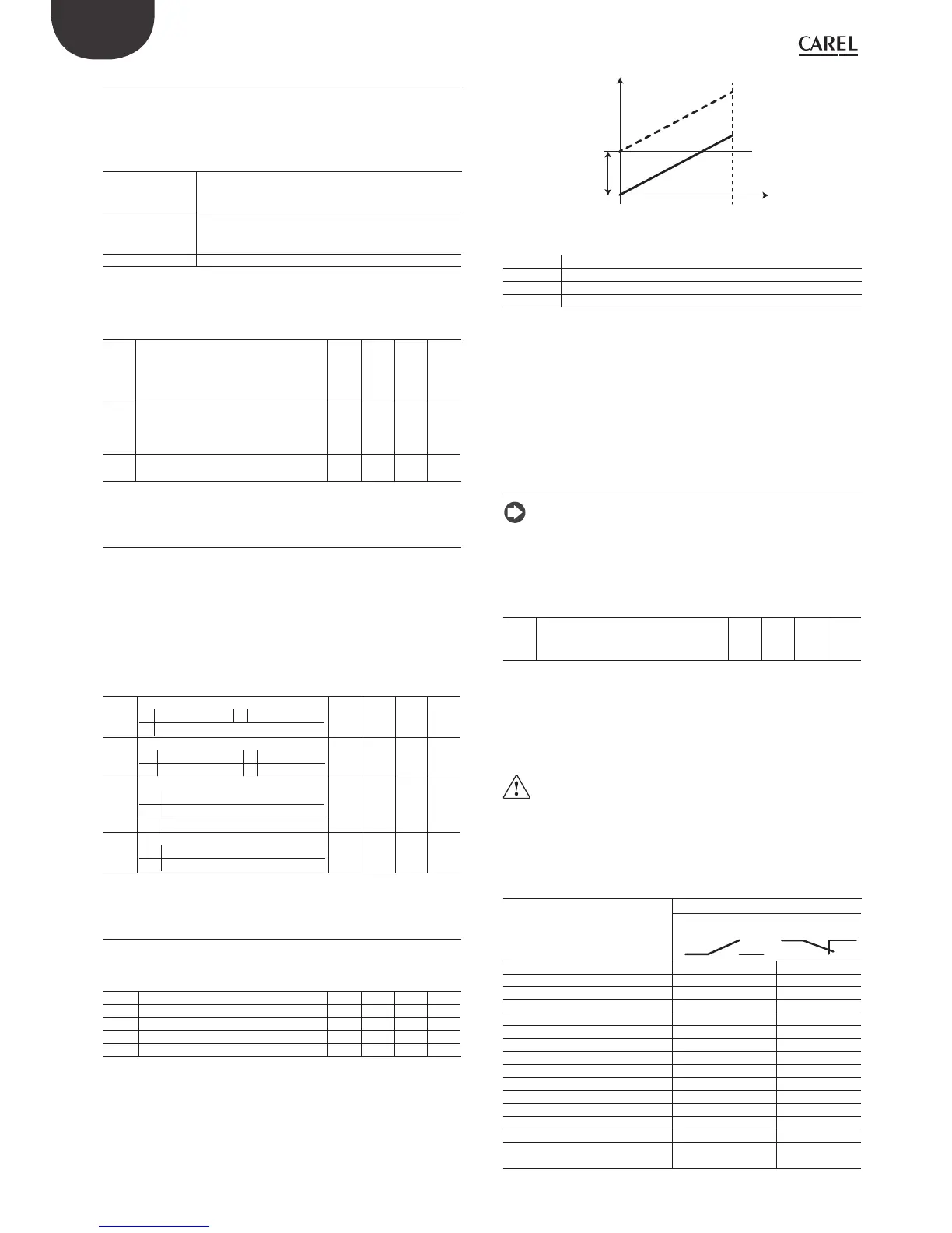
4.6.4 Probes reading correction
The values read by the probes can be corrected by adding/removing an
off set from the measure with the parameters /c1, ..., /c5.
Par. Description Def Min Max U.M.
/c1 Off set B1 0 -20.0 20.0 -
/c2 Off set B2 0 -20.0 20.0 -
/c3 Off set B3 0 -20.0 20.0 -
/c4 Off set B4 0 -20.0 20.0 -
/c5 Off set B5 0 -20.0 20.0 -
The off set may need to comply with HACCP requirements. In this case,
the off set should be calculated using a calibrated instrument. Setting
these parameters aff ects the measurement and the value shown on the
display, and consequently may not be allowed. If in doubt, contact the
food safety manager or site manager.
T1
T2
min max
A
Fig. 4.l
Key
T1 Temperature measured by the probe
T2 Temperature measured by the probe after off set correction
AOff set value
min, max Measurement range
HACCP - CAUTION
The modifi cation of these parameters, infl uencing the measurement and
display, may not be allowed in some applications or might require special
approval because it may aff ect the operation of HACCP systems.
If in doubt, consult the person in charge of food safety or the manager
of the plant.
4.6.5 Digital inputs
Note: the digital input 1 (DI1) is suited for door switch and is not
programmable.
If the door switch is not used, input DI1 can be disabled, and will no
longer be available for other functions, by setting A3=1
Par. Description Def Min Max U.M.
A3 Disable door microswitch
0= enabled
1= disabled
001-
If A3=0 and the door microswitch is not connected, the controller will
activate the "door open" icon. To prevent incorrect messages being
displayed, set A3=1 or short-circuit pin 21 (DI1) to one of the GND pins.
You can link multiple contacts to multifunction digital inputs to activate
various functions, such as alarm, enable / start defrost, low pressure, etc..
Caution: in order to ensure the safety of the unit in the event of
serious alarms, all the electromechanical safety devices required
to guarantee correct operation must be fi tted on the unit.
Operation of the digital inputs DI2, DI3
PARAMETERS A5, A9
Selection Contacts
OPEN CLOSE
0 = Not active - -
1 = Immediate external alarm active not active
2 = Do not select - -
3 = Enable defrost not enabled enabled
4 = Start defrost not active active
5 = Do not select - -
6= Remote On/Off OFF ON
7 = Do not select - -
8 = Low pressure switch low pressure status normal status
9 = Do not select - -
10 = Do not select - -
11 = Do not select - -
12 = AUX activation deactivated activated
13 = Do not select - -
14 = Continuous cycle activation contact opening
(deactivation)
contact closing
(activation)
Tab. 4.c
 Loading...


