SERViCE MANUAL
Paragraphs 42-44
denser and tie condenser and hoses back out of the
way. Unbolt and remove lower radiator seal strip. Re-
move wiring harness from fan shroud and lay rear-
ward. Remove radiator side plate bolts, then unbolt
and remove upper radiator air baffle. Remove upper
and lower radiator
hoses.
Unbolt and remove radiator.
If so equipped, unbolt and remove front weights
and weight bracket. Remove front axle assembly as
in paragraph 4, 5 or 8 and front support as in para-
graph 7 or 9. Identify and disconnect heater hoses
if so equipped, at front of engine. Remove fan, fan
belt and air conditioner compressor drive belt. Un-
bolt and remove the alternator and disconnect
tachometer cable. Disconnect water manifold hose
clamp. Remove fan spacer and water pump pulley.
Unbolt and remove water pump and carrier assem-
bly. Remove three cap screws and flat washer, tap
crankshaft pulley with a plastic hammer to loosen
clamping ring or pressure rings, then remove crank-
shaft pulley. Remove timing gear cover and oil pan
front bolts, then pull cover forward off the dowels
and remove from engine.
Use new gaskets and reinstall timing gear cover by
reversing the removal procedure. Tighten cover re-
taining cap screws and water pump and carrier re-
taining cap screws to a torque of 19 ft.-lbs. (26 N-m).
Tighten crankshaft pulley retaining cap screws in
three steps, to a torque of 22 ft.-lbs. (30 N-m) in first
step,
44 ft.-lbs. (60 N-m) in second step and 47 ft.-
lbs.
(65 N*m) in the final step.
TiMiNG GEARS
Aii Modeis
42.
CRANKSHAFT GEAR. Crankshaft gear is a
shrink fit on crankshaft. Ib renew the gear, it is rec-
ommended that crankshaft be removed from engine.
Then, using a hammer and chisel, split the gear at
its timing slot.
The roll pin for indexing crankshaft gear on crank-
shaft must protrude approximately 5/64 inch (2.0
mm).
Heat new gear to 400° F (204° C) and install
it against bearing journal.
WARNiNG: Aiways wear heat protective gioves
when handiing heated parts.
Make certain all timing marks are aligned as shown
in Fig. 52.
43.
CAMSHAFT GEAR. Camshaft gear is a shrink
fit on the camshaft. To renew the gear, remove cam-
shaft as outlined in paragraph 46. Gear can now be
pressed off in conventional manner, using care not
to damage the tachometer drive slot in end of
camshaft.
Before reinstalling, check thickness of thrust plate.
If thrust plate thickness is less than 0.274 inch (6.96
mm),
renew the plate.
When reassembling, install thrust plate and
Woodruff key. Heat gear to 400° F (204° C) and in-
stall it on camshaft, setting thrust plate clearance to
0.004-0.018 inch (0.10-0.45 mm).
WARNiNG: Aiways wear heat protective gioves
when handiing heated parts.
Install camshaft assembly and make certain all tim-
ing marks are aligned as shown in Fig. 52.
44.
IDLER GEAR. Ib remove idler gear, first re-
move timing gear cover as outlined in paragraph
41.
Idler gear shaft is attached to front of engine by a
special (left hand thread) cap screw.
Idler gear is equipped with two renewable needle
bearings. A spacer is used between the bearings.
When installing idler gear, coat threads of special
cap screw with Loctite 41 and tighten cap screw to
a torque of
72-76
ft.-lbs. (100-105
N-m).
End clearance
of gear on shaft should be 0.008-0.013 inch (0.20-0.33
mm).
Align timing marks on all timing gears as shown
in Fig. 52.
Timing gear backlash should be as follows:
Idler to crankshaft gear:
New gears 0.007-0.015 in.
(0.178-0.381 mm)
Used gears (max.) 0.027 in.
(0.686 mm)
Idler to camshaft gear:
New gears 0.0035-0.0106 in.
(0.089-0.269 mm)
Used gears (max.) 0.0226 in.
(0.574 mm)
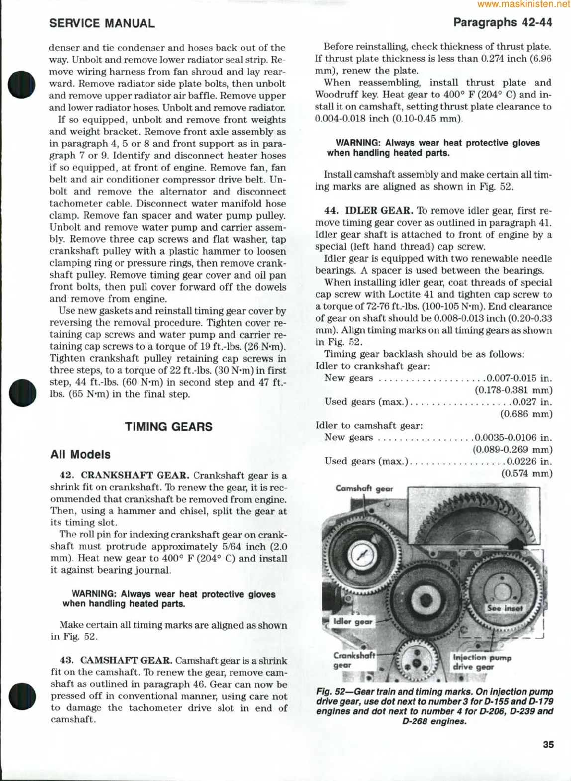
Fig. 52—Gear train and timing marks. On injection pump
drive
gear,
use dot next to number 3 for D-155 and D-179
engines and dot next to number 4 for
D-206,
D'239 and
D-268 engines.
35