Paragraphs 100-101
CASE/iNTERNATiONAL
signs of scoring or other damage, renew cylinder as-
sembly. Reassemble and reinstall by reversing disas-
sembly and removal procedures. Bleed air from sys-
tem as in paragraph 100. Adjust pedal height as in
paragraph 98.
Ib remove clutch slave cylinder, remove floor mat
and inspection panel from floor. Disconnect hose
from slave cylinder. Remove linkage return spring.
Remove the two snap rings and linkage pin. Unbolt
and remove slave cylinder.
Ib disassemble the slave cylinder, remove eye cle-
vis
(7—Fig.
83). Remove rubber boot (6) and snap ring
(5),
then withdraw piston (4) with seal (3). Remove
seal from piston. Clean and inspect piston and cylin-
der housing (2) for scoring or other damage. If scored
or damaged, renew cylinder assembly. A service kit
consisting of bleed screw rubber cap
(1),
seal
(3),
snap
ring (5) and rubber boot (6) is available. Reassemble
and reinstall by reversing the disassembly and
removal procedures. When installing eye clevis (7) on
piston (4), apply Loctite 270 to first three threads of
piston rod. Adjust eye clevis so that a distance of 3.4
inches (86.0 mm) is obtained between centers of cyl-
inder mounting holes and eye clevis hole (with pis-
ton fully inward). Bleed air from system as outlined
in paragraph 100.
100.
BLEED CLUTCH SYSTEM. Ib bleed air from
system, remove bleed screw cap
(1—Fig.
83) and con-
nect a length of transparent hose with its free end
in Hy-Tran Plus fluid. Loosen bleed screw. Fill reser-
voir with Hy-Tran Plus MS 1207 fluid to maximum
level mark. Fully press and release clutch pedal. Re-
peat as required until fluid free of air bubbles flows
through the hose. Then, tighten bleed screw while
holding pedal down.
NOTE:
Maice certain that fluid ievei in reservoir is
icept above minimum ievei mark during bieeding op-
eration.
Remove bleed hose and refill reservoir with fluid.
R&R AND OVERHAUL CLUTCH
Aii Models
101.
Ib remove engine clutch, it is first necessary
to detach (split) engine from clutch housing as fol-
lows:
Disconnect battery cables and remove battery.
Remove hood, grille and side panels. Disconnect
tachometer cable, starter wiring and rear wiring con-
nector. Shut off fuel and disconnect supply line and
fuel return line. Cap all openings. Disconnect ir\jec-
tion pump speed control and shut off cables. Identi-
fy and disconnect oil cooler lines and steering lines
and cap all openings. On models so equipped, discon-
nect heater hoses and air conditioning lines. On
models equipped with front drive axle, remove drive
shaft shield and front drive shaft. If available, attach
a split stand under clutch housing and engine oil pan
or block up under clutch housing and attach a hoist
to engine. Place wood blocks between front axle and
Fig. 82—Expioded view of dutch master cylinder used
on models equipped with cab.
1.
Housing 6. Seal
2.
Seal 7. Push rod
3.
Valve stem 8. Retaining washer
4.
Wave washer 9. Snap ring
5.
Plunger 10. Rubber boot
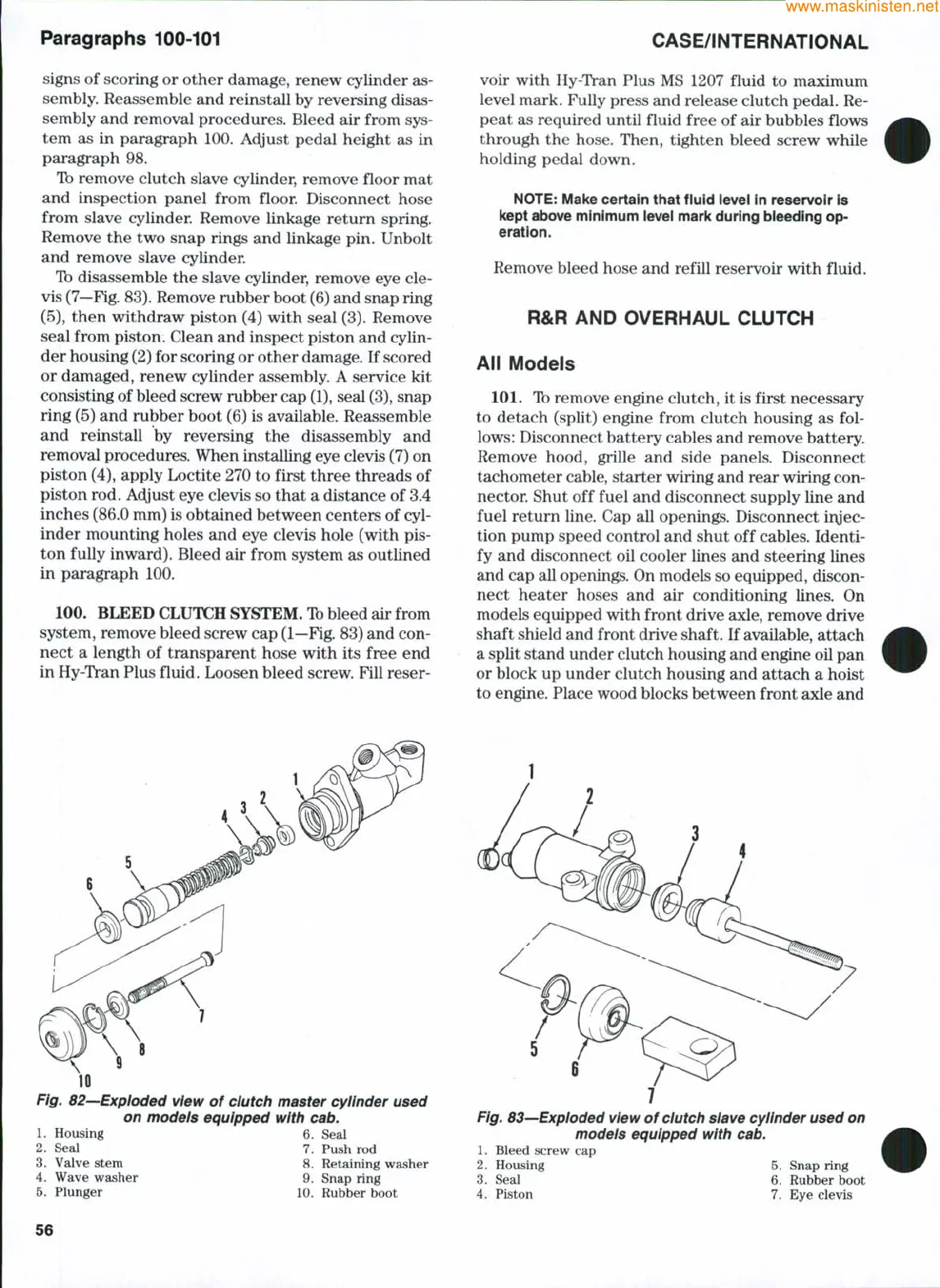
Fig. 83—Expioded view of clutch slave cyiinder used on
modeis equipped with cab.
1.
Bleed screw cap
2.
Housing 5. Snap ring
3.
Seal 6. Rubber boot
4.
Piston 7. Eye clevis
56