Paragraphs 4-5
CASE/iNTERNATiONAL
rearward from axle. Remove cap screws (1), caps (2)
and gaskets (3). Remove nut and lockwasher from
lock pin
(15).
Drive lock pin forward out of axle main
member Using a hammer and punch, drive kingpin
(12) out of axle and spindle. Remove spindle, thrust
bearing (14) and shim (13) if so equipped.
Inspect kingpin bushings (4) and renew if neces-
sary. Bushings should be installed until inner ends
of bushings are 0.016-0.031 inch (0.4-0.8 mm) below
the inside surfaces of spindle bores. Lubrication
grooves in bushings must align with lubrication
fittings.
Install a new thrust bearing (14), with TOP mark
up,
on bottom inside edge of spindle. Install spindle
over end of axle main member with thrust bearing
under axle. Use a jack to hold spindle and bearing
tight against bottom of axle. Using a feeler gage,
measure gap between upper edge of axle and the
spindle. If gap is more than 0.005 inch (0.127 mm),
install shims to reduce gap to less than 0.005 inch
(0.127 mm). Shims are available in thicknesses of
0.005 and 0.010 inch (0.127 and 0.254 mm).
Inspect kingpin (12) and renew as necessary. Install
kingpin with flat nearest to the top and in alignment
with hole for the lock pin
(15).
Install lock pin, lock-
washer and nut. Tighten nut securely. Install steer-
ing arm and tighten bolts (22) and nuts to a torque
of 160-180 ft.-lbs. (217-244 N-m). Install lubrication
fitting in steering arm.
Check oil seal (1—Fig. 2) and install new seal, if
needed, then install hub and adjust bearings as out-
lined in paragraph 1.
AXLE MAiN MEMBER AND PiVOT PiN
All Modeis With Adjustabie Axies
4.
REMOVE AND REINSTALL. 1b remove axle
main member (13—Figs. 3, 4 and 5), first block rear
wheels securely and apply park
brake.
If
so
equipped,
remove front weights and weight bracket. Unbolt and
remove front cover. Support tractor with stands un-
der side rails or oil pan, and remove front wheels.
Disconnect tie rod ends from left and right steering
arms (2 and 6). Unbolt and remove axle extensions
(4 and 5) with spindle assemblies. Identify and dis-
connect steering cylinder hoses at cylinder. Cap and
plug all openings. Remove the cylinder anchor clevis
pin. Straighten corners of lock plate (21) and remove
cap screws (22), lock plate (21) and cylinder retain-
ing bar (20). Hold cylinder upward and slide cylin-
der clevis from anchor on axle. Remove steering cyl-
inder. Remove center steering arm (19) and tie rods.
Place a floor jack under axle main member
(13).
Re-
move cap screws (16) and thread a slide hammer
puller into front end of pivot pin
(15).
Remove pivot
pin, then lower axle main member and remove from
under tractor.
Inspect axle pivot bushings
(14)
and renew if neces-
sary, aligning lubrication holes with lubrication fit-
tings.
Inspect cylinder pivot bushings (18) and steer-
ing arm pivot bushings (17) and renew as necessary.
Reinstall by reversing removal procedure, keeping
the following points in mind: Tighten cap screws (16)
and (22) to a torque of 80-90 ft.-lbs. (110-124 N-m).
Bend corners of lock plate (21) against flat of bolt
head (22). Tighten nuts on shoulder bolts (12) to a
torque of 246-272 ft.-lbs. (334-369 N-m). Tighten tie
rod end slotted nuts to a torque of 50 ft.-lbs. (68 N-m).
Aii Modeis With Nonadjustabie Cast Axle
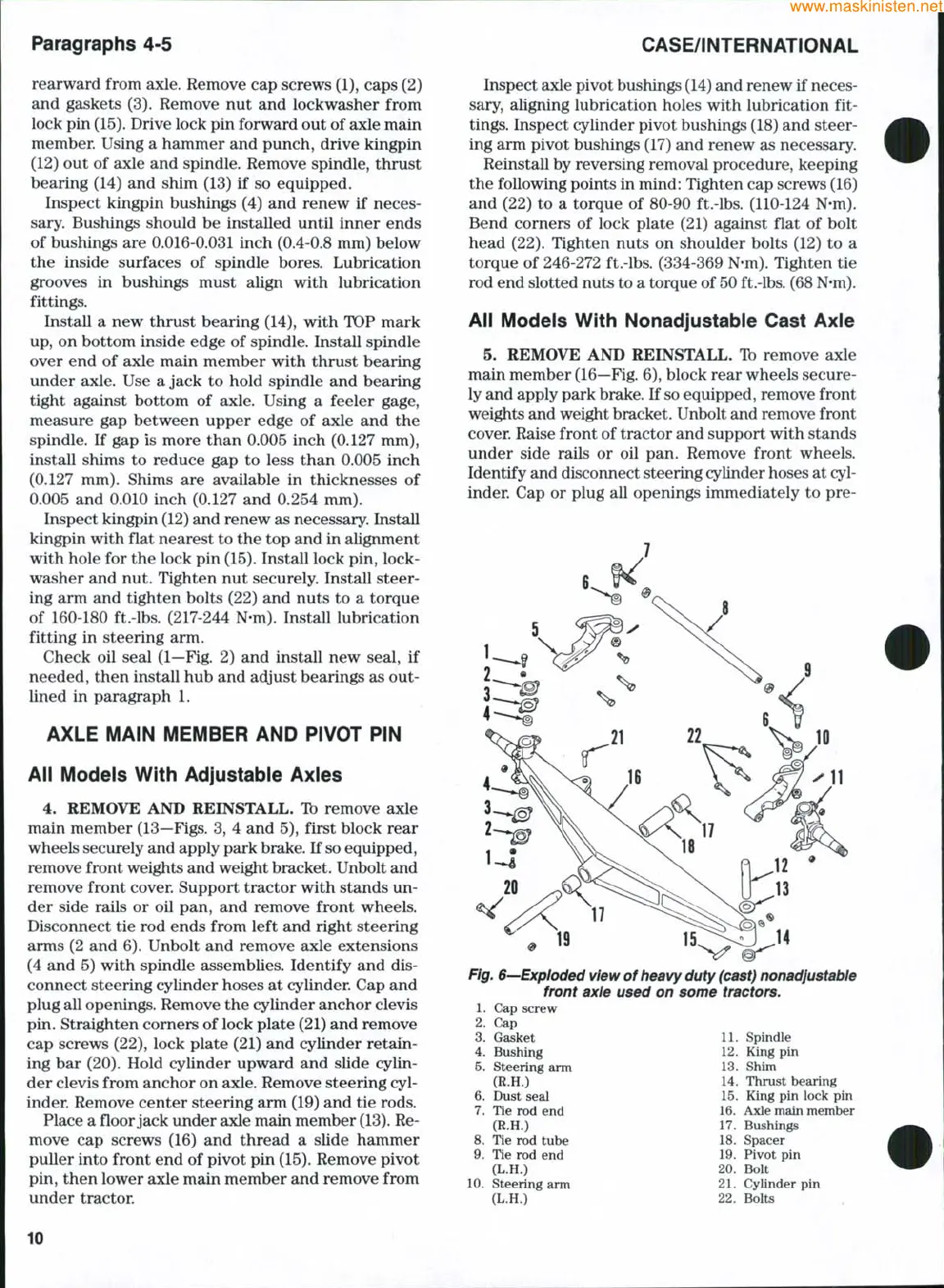
5. REMOVE AND REINSTALL. Ib remove axle
main member
(16—Fig.
6), block rear wheels secure-
ly and apply park
brake.
If
so
equipped, remove front
weights and weight bracket. Unbolt and remove front
cover. Raise front of tractor and support with stands
under side rails or oil pan. Remove front wheels.
Identify and disconnect steering cylinder hoses at cyl-
inder. Cap or plug all openings immediately to pre-
Fig.
6-—Exploded
view of heavy duty
(cast) nonadjustable
front axle used on some tractors.
1.
Cap screw
2.
Cap
Gasket 11. Spindle
3.
4.
Bushing
5.
Steering arm
(R.H.)
6. Dust seal
7.
Tie rod end
(R.H.)
8. Tie rod tube
9. Tie rod end
(L.H.)
Steering arm
(L.H.)
10
12.
King pin
13.
Shim
14.
Thrust bearing
15.
King pin lock pin
16.
Axle main member
17.
Bushings
18.
Spacer
19.
Pivot pin
20.
Bolt
21.
Cylinder pin
22.
Bolts
10
 Loading...


