Paragraph 109 (Cont.)
CASE/INTERNATIONAL
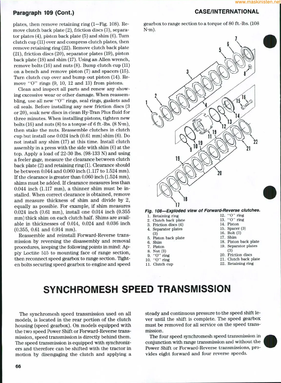
plates,
then remove retaining ring (1—Fig. 108). Re-
move clutch back plate
(2),
friction discs
(3),
separa-
tor plates (4), piston back plate (5) and shim
(6).
Turn
clutch cup
(11)
over and compress clutch plates, then
remove retaining ring
(22).
Remove clutch back plate
(21),
friction discs (20), separator plates (19), piston
back plate (18) and shim
(17).
Using an Allen wrench,
remove bolts (16) and nuts
(8).
Bump clutch cup (11)
on a bench and remove piston (7) and spacers (15).
Turn clutch cup over and bump out piston (14). Re-
move "0" rings (9, 10, 12 and 13) from pistons.
Clean and inspect all parts and renew any show-
ing excessive wear or other damage. When reassem-
bling, use all new
**0**
rings, seal rings, gaskets and
oil seals. Before installing any new friction discs (3
or
20),
soak new discs in clean Hy-Tran Plus fluid for
three minutes. When installing pistons, tighten new
bolts (16) and nuts (8) to a torque of 6 ft.-lbs. (8 N-m),
then stake the nuts. Reassemble clutches in clutch
cup but install one 0.024 inch
(0.61
mm) shim
(6).
Do
not install any shim (17) at this time. Install clutch
assembly in a press with the side with shim (6) at the
top.
Apply a load of 22-30 lbs. (98-133 N) and using
a feeler gage, measure the clearance between clutch
back plate (2) and retaining ring
(1).
Clearance should
be between 0.044 and 0.060 inch (1.117 to 1.524 mm).
If the clearance is greater than 0.060 inch (1.524 mm),
shims must be added. If clearance measures less than
0.044 inch (1.117 mm), a thinner shim must be in-
stalled. When correct clearance is obtained, remove
and measure thickness of shim and divide by 2,
equally as possible. For example, if shim measures
0.024 inch (0.61 mm), install one 0.014 inch (0.355
mm) thick shim on each clutch
half.
Shims are avail-
able in thicknesses of 0.014, 0.024 and 0.036 inch
(0.355,
0.61 and 0.914 mm).
Reassemble and reinstall Forward-Reverse trans-
mission by reversing the disassembly and removal
procedures, keeping the following points in mind: Ap-
ply Loctite 515 to mounting face of range section,
then reconnect speed gearbox to range section. Tight-
en bolts securing speed gearbox to engine and speed
gearbox to range section to a torque of
80
ft.-lbs. (108
N-m).
Fig. 108—Exploded view of Forward-Reverse clutches.
1.
Retaining ring 12. "0" ring
2.
Clutch back plate 13. "0" ring
3.
Friction discs (4) 14. Piston
4.
Separator plates 15. Spacer (3)
(3) 16. Bolt (3)
5.
Piston back plate 17. Shim
6. Shim 18. Piston back plate
7.
Piston 19. Separator plates
8! Nut (3) (3)
9. *'O" ring 20. Friction discs
10.
"Oaring 21. Clutch back plate
11.
Clutch cup 22. Retaining ring
SYNCHROMESH SPEED TRANSMISSION
The synchromesh speed transmission used on all
models, is located in the rear portion of the clutch
housing (speed gearbox). On models equipped with
the two speed Power Shift or Forward-Reverse trans-
mission, speed transmission is directly behind them.
The speed transmission is equipped with synchroniz-
ers and therefore can be shifted with the tractor in
motion by disengaging the clutch and applying a
steady and continuous pressure to the speed shift le-
ver until the shift is complete. The speed gearbox
must be removed for all service on the speed trans-
mission.
The four speed synchromesh speed transmission in
conjunction with range transmission and without the
Power Shift or Forward-Reverse transmissions, pro-
vides eight forward and four reverse speeds.
66
 Loading...


