SERViCE MANUAL
Paragraph 115
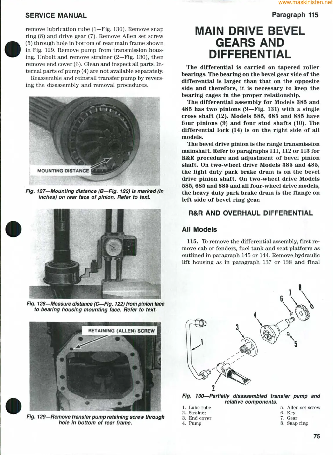
remove lubrication tube (1—Fig. 130). Remove snap
ring (8) and drive gear (7). Remove Allen set screw
(5) through hole in bottom of rear main frame shown
in Fig. 129. Remove pump from transmission hous-
ing. Unbolt and remove strainer (2—Fig. 130), then
remove end cover
(3).
Clean and inspect all parts. In-
ternal parts of pump (4) are not available separately.
Reassemble and reinstall transfer pump by revers-
ing the disassembly and removal procedures.
MOUNTING DISTANCE
Fig. 127—Mounting distance (B—Fig. 122) is marked (In
inches) on rear face of pinion. Refer to
text.
Fig.
128—Measure distance
(C—Fig.
122) from pinion Uice
to bearing housing mounting face. Refer to
text.
RETAfNiNG (ALLEN) SCf^W
MAIN DRIVE BEVEL
GEARS AND
DiFFERENTiAL
The differential is carried on tapered roller
bearings. The bearing on the bevel gear side of the
differential is larger than that on the opposite
side and therefore, it is necessary to keep the
bearing cages in the proper relationship.
The differential assembly for Models 385 and
485 has two pinions (9—Fig. 131) with a single
cross shaft (12). Models 585, 685 and 885 have
four pinions (9) and four stud shafts (10). The
differential lock (14) is on the right side of all
models.
The bevel drive pinion is the range transmission
mainshaft. Refer to paragraphs 111, 112 or 113 for
R&R procedure and adjustment of bevel pinion
shaft. On two-wheel drive Models 385 and 485,
the light duty park brake drum is on the bevel
drive pinion shaft. On two-wheel drive Models
585,
685 and 885 and all four-wheel drive models,
the heavy duty park brake drum is the flange on
left side of bevel ring gear.
R&R AND OVERHAUL DiFFERENTiAL
All Models
115.
Ib remove the differential assembly, first re-
move cab or fenders, fuel tank and seat platform as
outlined in paragraph 145 or 144. Remove hydraulic
lift housing as in paragraph 137 or 138 and final
Fig,
129—Remove
transfer pump
retaining
screw
through
hoie in bottom of rear frame.
Fig. 130—Partiaily disassembled transfer pump and
relative components.
5.
Allen set screw
6. Key
7.
Gear
1.
Lube tube
2.
Strainer
3.
End cover
4.
Pump
8. Snap ring
75