SERViCE MANUAL
Paragraph 56
Inspect face of flywheel and if face is grooved more
than 0.025 inch (0.64 mm) or if face is worn
out-of-
flat more than 0.006 inch (0.152 mm), renew or reface
flywheel. A maximum of 0.125 inch (3.17 mm) can
be removed from flywheel face.
NOTE:
The same amount of material removed
from fiywheei face must be removed from pressure
piate mounting surface on fiywheei.
Tighten flywheel retaining cap screws in three
steps:
30 ft.-lbs. (40 N-m) in the first step, 60 ft.-lbs.
(80 (N-m) in the second step and
110
ft.-lbs. (150 N-m)
in the final step.
ENGiNE BALANCER
Modeis So Equipped
56.
R&R AND OVERHAUL. All D-206, D-239 and
D-268 engines are equipped with an engine balancer
which is mounted on underside of engine crankcase.
Balancers are driven by a renewable gear
(2—Fig.
53)
which is a shrink fit on crankshaft. The balancer con-
sists of two unbalanced gear weights which rotate in
opposite directions at twice crankshaft speed. They
produce forces which tend to counteract the vibra-
tion which is inherent in four cylinder engines hav-
ing a single plane crankshaft (1 and 4 throws dis-
placed 180 degrees from throws 2 and 3). It is
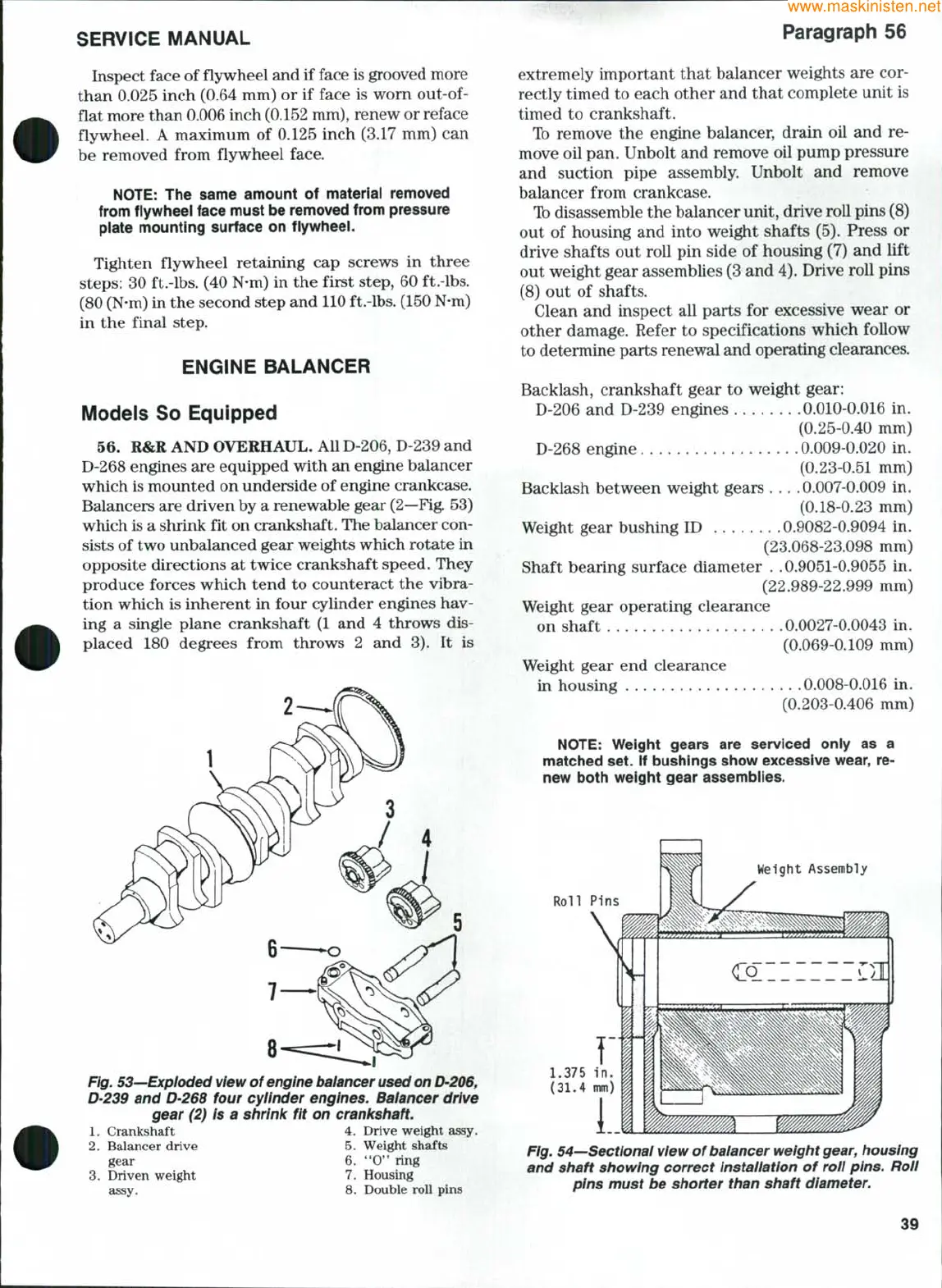
Fig. 53—Exploded
view
of
engine baiancer used
on
D-206,
D-239 and D'268 four cyiinder engines. Balancer drive
gear (2) is a shrink fit on crankshaft.
1.
Crankshaft 4. Drive weight assy.
2.
Balancer drive 5. Weight shafts
gear 6.
**0'*
ring
3.
Driven weight 7. Housing
assy. 8. Double roll pins
extremely important that balancer weights are cor-
rectly timed to each other and that complete unit is
timed to crankshaft.
Ib remove the engine balancer, drain oil and re-
move oil pan. Unbolt and remove oil pump pressure
and suction pipe assembly. Unbolt and remove
balancer from crankcase.
Ib disassemble the balancer unit, drive roll pins (8)
out of housing and into weight shafts (5). Press or
drive shafts out roll pin side of housing (7) and lift
out weight gear assemblies (3 and 4). Drive roll pins
(8) out of shafts.
Clean and inspect all parts for excessive wear or
other damage. Refer to specifications which follow
to determine parts renewal and operating clearances.
Backlash, crankshaft gear to weight gear:
D-206 and D-239 engines 0.010-0.016 in.
(0.25-0.40 mm)
D-268 engine 0.009-0.020 in.
(0.23-0.51 mm)
Backlash between weight gears .... 0.007-0.009 in.
(0.18-0.23 mm)
Weight gear bushing ID 0.9082-0.9094 in.
(23.068-23.098 mm)
Shaft bearing surface diameter . .0.9051-0.9055 in.
(22.989-22.999 mm)
Weight gear operating clearance
on shaft 0.0027-0.0043 in.
(0.069-0.109 mm)
Weight gear end clearance
in housing 0.008-0.016 in.
(0.203-0.406 mm)
NOTE:
Weight gears are serviced oniy as a
matched set. if bushings show excessive wear, re-
new both weight gear assembiies.
Weight Assembly
l
Roll Pins
1.375 in.
(31.4 mm)
i..
Fig. 54—Sectional view of baiancer weight
gear,
housing
and shaft showing correct instaiiation of roll pins. Roll
pins must be shorter than shaft diameter.
39