Paragraphs 57-58
When reassembling, make certain that oil passages
in housing and shafts are clean. Lubricate shafts and
weight gear bushings and place drive weight gear (4)
in housing. Install weight shaft from roll pin side of
housing through the weight gear. Align roll pin hole
in shaft with roll pin hole in housing, then tap shaft
into position. Install double roll pins (8) as shown in
Fig. 54.
NOTE:
Roii pins must be shorter than shaft di-
ameter.
Install roll pins to a depth of 1.375 inches (31.4 mm)
in roll pin bosses. Place idler weight in housing and
with both weights down, mesh teeth so that timing
marks are aligned. Install second shaft and secure
with double roll pin. Using a dial indicator, check
backlash between weight gears. Backlash should be
0.007-0.009 inch (0.18-0.23 mm). If backlash is exces-
sive,
renew weight gear assemblies.
Ib install balancer assembly, first rotate crankshaft
to position number two piston at TDC of compres-
sion stroke. Place new '*0" ring
(6—Fig.
53) in recess
on balancer. Then, with weights toward bottom of
balancer housing and weight gear timing marks
aligned, install balancer so that timing mark on
balancer drive weight is aligned with timing mark on
balancer drive gear (2). Use new ''0" rings and in-
stall oil pump pressure and suction pipe assembly. Us-
ing a dial indicator, check backlash between balancer
drive weight gear (4) and balancer drive gear (2).
Backlash should be 0.010-0.016 inch (0.25-0.40 mm)
on D-206 and D-239 engines or 0.009-0.020 inch
(0.23-
0.51 mm) on D-268 engine.
NOTE:
When baci(iash between weight gears is
satisfactory and baci(iash between weight gear (4)
and baiancer drive gear (2) is excessive, drive gear
(2) is excessiveiy worn and shouid be renewed.
Install oil pan with new pan gasket and fill crank-
case to proper level with new oil.
57.
RENEW BALANCER DRIVE GEAR. Ib re-
new balancer drive gear (2—Fig. 53), first remove
crankshaft from engine. Remove worn or damaged
drive gear by using a chisel and hammer and split-
ting the gear. Remove any burrs which migiit be pres-
ent on gear mounting surface of crankshaft. Heat
new gear to 360-390° F (180-200° C), align the sin-
gle timing mark (below tooth space of drive gear)
with the notch on crankshaft flange and slide drive
gear on crankshaft. The two marked teeth on drive
gear should be toward flywheel end of crankshaft.
WARNiNG: Aiways wear heat protective gioves
when handiing heated parts.
CASE/iNTERNATiONAL
OiL PUMP AND RELiEF VALVE
Aii Modeis
58.
The internally mounted gear type oil pump is
driven from the crankshaft gear and is accessible af-
ter removing the oil pan on all models and the tim-
ing gear cover on D-206, D-239 and D-268 engines.
The pump is mounted to the front main bearing cap
on all models.
On D-155 and D-179 engines, remove the main bear-
ing cap and oil pump as an assembly. Leave bearing
cap on pump when repairing oil pump.
On D-206, D-239 and D-268 engines, use an Allen
wrench and remove the two upper pump retaining
bolts,
then working through holes in idler gear, re-
move the remaining two retaining
bolts.
Unbolt pres-
sure and suction pipe assembly, then remove oil
pump assembly.
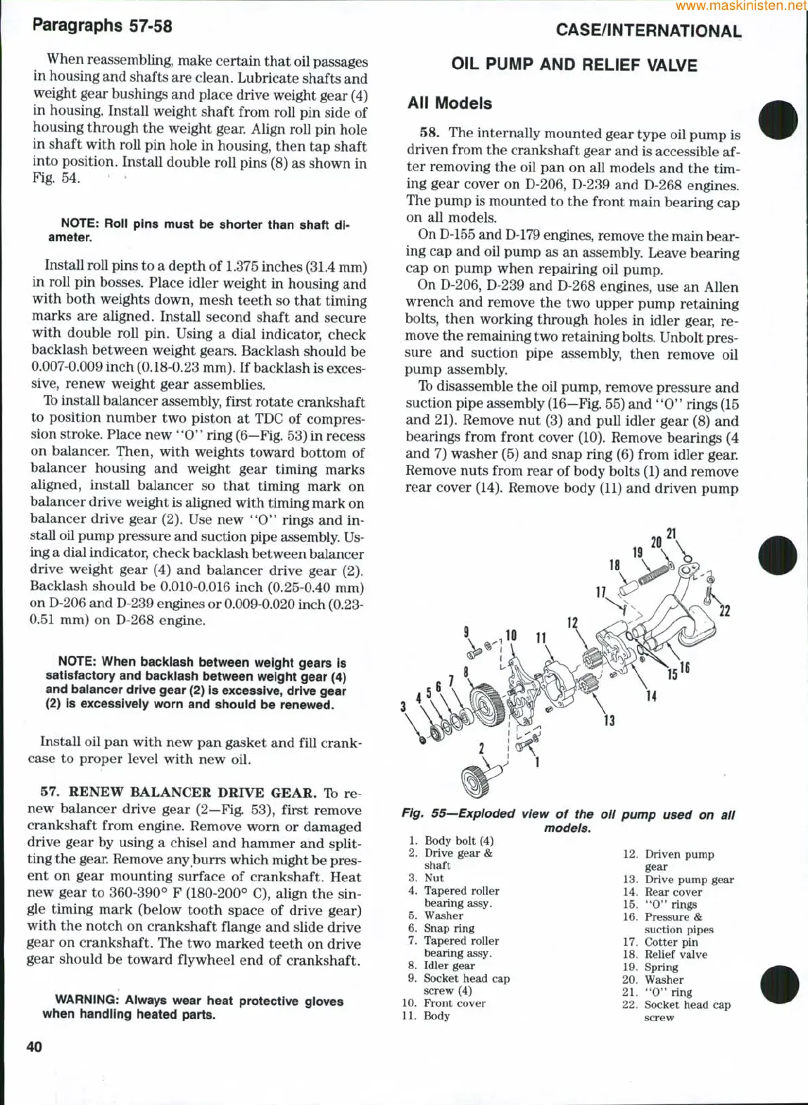
Ib disassemble the oil pump, remove pressure and
suction pipe assembly
(16—Fig.
55) and
**0"
rings (15
and 21). Remove nut (3) and pull idler gear (8) and
bearings from front cover (10). Remove bearings (4
and 7) washer (5) and snap ring (6) from idler gear.
Remove nuts from rear of body bolts (1) and remove
rear cover (14). Remove body (11) and driven pump
Fig. 55—Exploded
1.
Body bolt (4)
2.
Drive gear &
shaft
3.
Nut
4.
Tapered roller
bearing assy.
5.
Washer
6. Snap ring
7.
Tapered roller
bearing assy.
8. Idler gear
9. Socket head cap
screw (4)
10.
Front cover
11.
Body
view of the oli pump used on all
models.
12.
Driven pump
gear
13.
Drive pump gear
14.
Rear cover
15.
*'O" rings
16.
Pressure &
suction pipes
17.
Cotter pin
18.
Relief valve
19.
Spring
20.
Washer
21.
"0" ring
22.
Socket head cap
screw
40