CASE/INTERNATIONAL
ROCKSHAFT
All Models
141.
REMOVE AND REINSTALL. Ib remove the
rockshaft (13—Fig. 167), first remove hydraulic lift
housing as in paragraph 137 or 138. Then, remove
work cylinder and valve assembly as in paragraph
139.
Disconnect and remove sensing linkage as re-
quired. Disconnect link from actuating hub (17). Re-
move retaining bolts and washers from both ends of
rockshaft. Place marks on lift arms in alignment with
timing marks on ends of rockshaft. Remove both lift
arms.
Loosen set screw (15) in bell crank (16). Loos-
en set screw (18) in actuating hub (17). Slide actuat-
ing hub off the Woodruff key (14) and remove the key.
Pull rockshaft
(13)
out left side of housing and remove
actuating hub and bell crank. Remove oil seals (7 and
11) and bushings (8 and 12) as required.
Reinstall by reversing the removal procedure. In-
stall oil seals
(7
and
11)
with lips facing inward. Lubri-
cate seals with petroleum jelly. Use Loctite 241 on
threads of set screws (15 and 18) and tighten secure-
ly. Align timing marks and install lift arms. Tighten
retaining bolts to a torque of 98-110 ft.-lbs. (133-149
N-m).
Paragraphs 140-141
nearest to closed end of piston. Install piston, closed
end first, into cylinder
Use all new
**0*'
rings and reassemble action valve
and control valve to cylinder, then reinstall the cyl-
inder and valve assembly into lift housing (9—Fig.
167).
Cushion relief (safety) valve (2) can be installed
in cylinder through hole in lift housing. Reinstall lift
housing as outlined in paragraph 137 or 138.
RAISE RATE VALVE
All Models
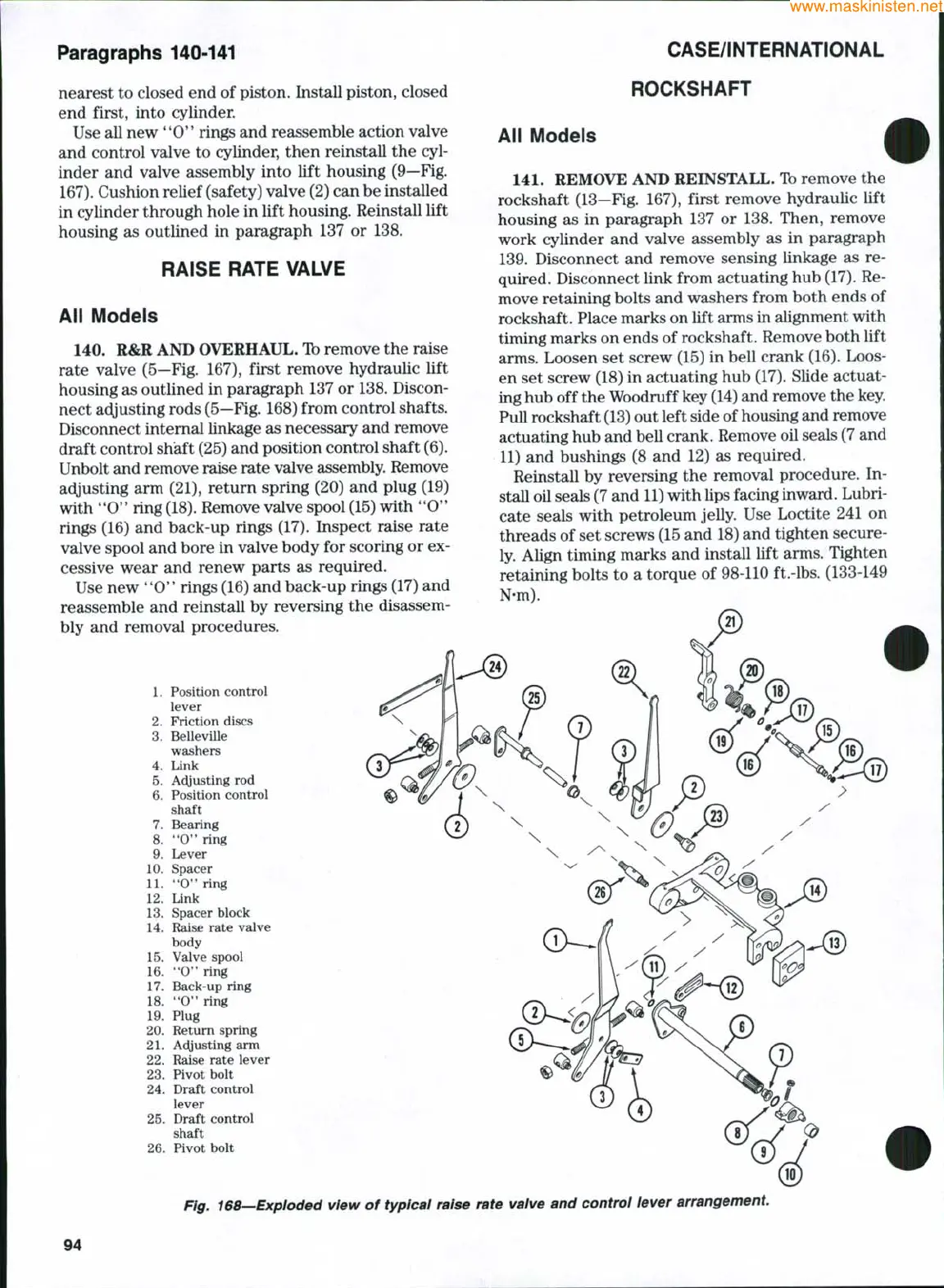
140.
R&R AND OVERHAUL. Ib remove the raise
rate valve (5—Fig. 167), first remove hydraulic lift
housing as outlined in paragraph 137 or 138. Discon-
nect adjusting rods
(5—Fig.
168) from control shafts.
Disconnect internal linkage as necessary and remove
draft control shaft (25) and position control shaft (6).
Unbolt and remove raise rate valve assembly. Remove
adjusting arm (21), return spring (20) and plug (19)
with
**0"
ring
(18).
Remove valve spool (15) with
**0'*
rings (16) and back-up rings (17). Inspect raise rate
valve spool and bore in valve body for scoring or ex-
cessive wear and renew parts as required.
Use new
"0**
rings (16) and back-up rings (17) and
reassemble and reinstall by reversing the disassem-
bly and removal procedures.
1.
Position control
lever
2.
Friction discs
3.
Belleville
washers
4.
Link
5.
Ai^justing rod
6. Position control
shaft
7.
Bearing
8. "O" ring
9. Lever
10.
Spacer
11.
**0*'
ring
12.
Link
13.
Spacer block
14.
Raise rate valve
body
15.
Valve spool
16.
"O" ring
17.
Back-up ring
18.
"0" ring
19.
Plug
20.
Return spring
21.
A(^usting arm
22.
Raise rate lever
23.
Pivot bolt
24.
Draft control
lever
25.
Draft control
shaft
26.
Pivot bolt
Fig. 168—Exploded view of typical raise rate valve and control lever arrangement.
94