Paragraphs 38-41
CASE/iNTERNATiONAL
ton at top dead center of compression stroke. Adjust
the four valves indicated on the chart shown in Fig.
50.
Turn engine one complete revolution to position
number four piston at TDC of compression stroke and
adjust the remaining four valves indicated on the
chart.
NOTE:
Vaive arrangement is exhaust-intake-
exhaust-intake and so on starting from front of cyi-
inder head.
VALVE GUiDES AND SPRiNGS
Aii Modeis
38.
Intake and exhaust valve guides are inter-
changeable. Guides should be pressed into cylinder
head using special tool 3055699R1 or equivalent, to
set distance from top of guide to seat of spring re-
cess to 1.102 inches (28 mm). After installation,
guides must be reamed to an inside diameter of
0.3940-0.3945 inch (10.00-10.02 mm). Valve stem to
valve guide diametral clearance should be 0.0016-
0.0025 inch (0.041-0.064 mm) for intake valves and
0.0025-0.0033 inch (0.064-0.084 mm) for exhaust
valves. Maximum allowable clearance in all guides is
0.006 inch (0.152 mm).
Intake and exhaust valve springs are also inter-
changeable. Springs should have a free length of 2.07-
2.18 inches (52.58-55.37 mm) and should test 145.5-
158.7 lbs. (647.2-705.90 N) when compressed to a
length of 1.346 inch (34.19 mm). Renew any spring
which is rusted, discolored or does not meet pressure
test specifications.
VALVE TAPPETS
(CAM FOLLOWERS)
Aii Modeis
39.
The 0.7862-0.7868 inch (19.97-19.98 mm) diam-
eter mushroom type tappets operate directly in the
unbushed crankcase bores. Clearance of tappets in
bores should be 0.0004-0.0023 inch (0.010-0.058 mm).
With
No.
1
Piston at TDC. (Compression)
No 4 Piston at T.D
C.
(Compression)
Adjust Valves (Engine Warm)
1
2
3
4
5
6 7
8
FRONT 12 3 4 5 6 7 8
Fig. 50—Chart shows vaive tappet adjusting procedure
for
D-206,
D''239 and D-268 four cylinder engines. Refer
to
text.
Ikppets can be removed after first removing the
crankcase side plate and the camshaft. Oversize tap-
pets are not available.
VALVE TAPPET LEVERS
(ROCKER ARMS)
Aii Modeis
40.
Removal of rocker arms and shaft assembly is
obvious after removal of rocker arm cover. Ib remove
rocker arms from shaft, remove bracket clamp bolts
and slide all parts from shaft. Outside diameter of
shaft is 0.848-0.850 inch (21.54-21.59 mm). Rocker
arms should have an operating clearance of
0.001-
0.003 inch (0.025-0.076 mm) on rocker shaft with a
maximum allowable clearance of 0.006 inch (0.152
mm).
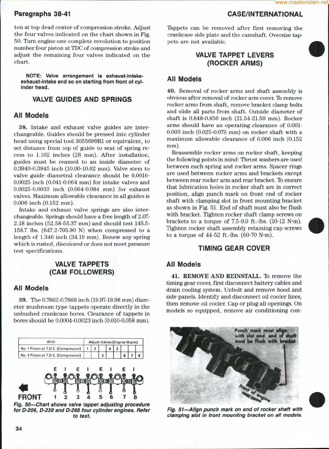
Reassemble rocker arms on rocker shaft, keeping
the following points in mind: Thrust washers are used
between each spring and rocker arms. Spacer rings
are used between rocker arms and brackets except
between rear rocker arm and rear bracket. Ib ensure
that lubrication holes in rocker shaft are in correct
position, align punch mark on front end of rocker
shaft with clamping slot in front mounting bracket
as shown in Fig. 51. End of shaft must also be flush
with bracket. Tighten rocker shaft clamp screws on
brackets to a torque of 7.5-9.0 ft.-lbs. (10-12 N-m).
Tighten rocker shaft assembly retaining cap screws
to a torque of 44-52 ft.-lbs. (60-70 N-m).
TiMiNG GEAR COVER
Aii Modeis
41.
REMOVE AND REINSTALL. Ib remove the
timing gear cover, first disconnect battery cables and
drain cooling system. Unbolt and remove hood and
side panels. Identify and disconnect oil cooler lines,
then remove oil cooler. Cap or plug all openings. On
models so equipped, remove air conditioning con-
mmk mytl
mytt
b%
Huih with brocl(«l
Fig. 51—Align punch mark on end of rocker shaft with
damping slot In front mounting bracket on aii modeis.
34
 Loading...


