Paragraph 61
When installing new filters, use new seal rings and
apply a light coat of oil to seal ring. Screw filters on
until seal ring contacts filter head, then hand tight-
en 1/2 to 3/4 turn. Close drain valve.
On all models without cab, diesel fuel is gravity fed
to filters. All models equipped with cab are equipped
with a hand primer pump. On models without cab,
open shut-off valve under right side of fuel tank. On
all models, open air vent screw on primary filter
head. On models with cab, actuate hand primer
1.
AIR REMOVAL
SCREW
3. UNION SCREW
4. SEAL
2.
FUEL PIPE
S.
PRIMARY FILTER
8. DRAIN VALVE
I FUEL FILTERS 3 CYLiNDER ENGiNE
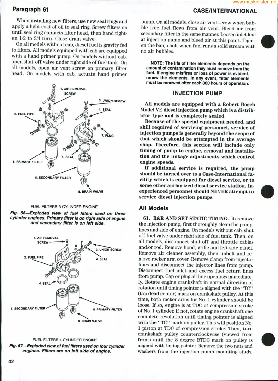
Fig. 56—Exploded view of fuel filters used on three
cylinder engines. Primary fiiter
is
on right side of engine
and secondary filter Is on left side.
1.
AIR REMOVAL
SCREW
2.
FUEL PIPE
3. UNION SCREW
4. SEAL
6. SECONDARY RLTER
5. PRIMARY FILTER
8. DRAIN VALVE
FUEL FILTERS 4 CYLINDER ENGINE
Fig.
57—Expioded view
of fuel
filters used on
four cylinder
engines. Filters are on left side of engine.
CASE/iNTERNATiONAL
pump. On all models, close air vent screw when bub-
ble free fuel flows from air vent. Bleed air from
secondary filter in the same manner Loosen inlet line
at injection pump and bleed air at this point. Tight-
en the bar\jo bolt when fuel runs a solid stream with
no air bubbles.
NOTE:
The life of fiiter eiements depends on the
amount of contamination they must remove from the
fuei.
if engine misfires or ioss of power is evident,
renew the eiements. in any event, fiiter eiements
must be renewed after each 800 hours of operation.
iNJECTiON PUMP
All models are equipped with a Robert Bosch
Model
VE
diesel iiyection pump which is a distrib-
utor type and is completely sealed.
Because of the special equipment needed, and
skill required of servicing personnel, service of
iivjection pumps is generally beyond the scope of
that which should be attempted in the average
shop.
Therefore, this section will include only
timing of pump to engine, removal and installa-
tion and the linkage acljustments which control
engine speeds.
If additional service is required, the pump
should be turned over to a Case-International fa-
cility which is equipped for diesel service, or to
some other authorized diesel service station. In-
experienced personnel should NEVER attempt to
service diesel iivjection pumps.
Aii Modeis
61.
R&R AND SET STATIC TIMING. Ib remove
the irvjection pump, first thoroughly clean the pump,
lines and side of
engine.
On models without cab, shut
off fuel valve under right side of fuel tank. Then, on
all models, disconnect shut-off and throttle cables
and/or rod. Remove hood, grille and left side panel.
Remove air cleaner assembly, then unbolt and re-
move rocker arm cover. Remove clamp from iryector
lines and disconnect the iryector lines from pump.
Disconnect fuel inlet and excess fuel return lines
from pump. Cap or plug all line openings immediate-
ly. Rotate engine crankshaft in normal direction of
rotation until timing pointer is aligned with the **TC'*
(top dead center) mark on crankshaft pulley. At this
time,
both rocker arms for No. 1 cylinder should be
loose. If so, engine is at TDC of compression stroke
of
No.
1
cylinder. If not, rotate engine crankshaft one
complete revolution until timing pointer is aligned
with the
**TC*'
mark on pulley. This will position No.
1 piston at TDC of compression stroke. Then, tum
crankshaft pulley counterclockwise (viewed from
front) until the 8 degree BTDC mark on pulley is
aligned with timing pointer. Remove the two nuts and
washers from the iryection pump mounting studs.
42