Paragraph 121
CASE/INTERNATIONAL
gear (11) and dowels (13). Then, using a pusher ar-
rangement, push on inner end of axle shaft to remove
axle and bearings.
Inspect bearings and seals for damage or wear and
renew as necessary.
Ib reassemble, install axle bearing cups (5 and 9)
and inner oil seal (14) in axle housing. If necessary,
install wear sleeve (3) in outer end of axle housing.
InstaU outer oil seal (2) and outer bearing cone (5)
on axle shaft.
NOTE:
On Row Crop modeis, outer oii seai can be
instaiied after axie siiaft is instailed in housing.
Pack inner and outer bearing cones with multipur-
pose grease. InstaU the axle into the housing and
drive the inner bearing cone (10) on axle until the
planetary carrier assembly can be instaUed. InstaU
and tighten cap screw (23) to draw axle shaft into
inner bearing cone. Remove the planetary assembly
and instaU ring gear
(11)
and secure with dowels (13).
Install a small piece of lead at end of axle shaft.
InstaU planetary assembly and bolt
(23).
Lock plane-
tary gear and ring gear by installing a rod between
the teeth. Then, tighten cap screw (23) until there
is 0.001-0.010 inch (0.025-0.254 mm) axle end play.
Check with dial indicator. Unbolt and remove the
planetary assembly. Remove the lead and measure
the thickness. Select shims
(21)
equal to that amount.
Shims are available in thicknesses of
0.007,
0.012 and
0.029 inch (0.178, 0.305 and 0.737 mm). Use petrole-
um jelly and stick shims to end of axle shaft. InstaU
planetary assembly and tighten the cap screw to a
torque of 220-250 ft.-lbs. (298-339 N-m). InstaU out-
er brake disc (12).
BRAKES
Brakes on all models, are self equalizing hydrau-
lic actuated wet type single disc brakes. Brakes
are located on the differential output shafts
(planetary drive shafts) and are accessible after
removing final drive units as outlined in para-
graph 118. Return hydraulic fluid from the oil
cooler maintains a full master cylinder by flow-
ing through a brake reservoir. Brake operation
can be accomplished with engine inoperative be-
cause of the reservoir which keeps master
cylinders filled. Also in the brake system is an
equalizer line between the master cylinders. This
line permits equal flow to both brake pistons
when both brake pedals are depressed. If one
brake is applied, the equalizer line does not
function.
Service (foot) brakes MUST NOT be used for
parking or any other stationary job which re-
quires the tractor to be held in position. Even a
small amount of fluid leakage would result in
brakes loosening and severe damage to equipment
or injury to personnel could result. USE PARK
BRAKE when parking tractor. Refer to paragraph
117 for park brake adjustment.
BRAKE ADJUSTMENT
All Models
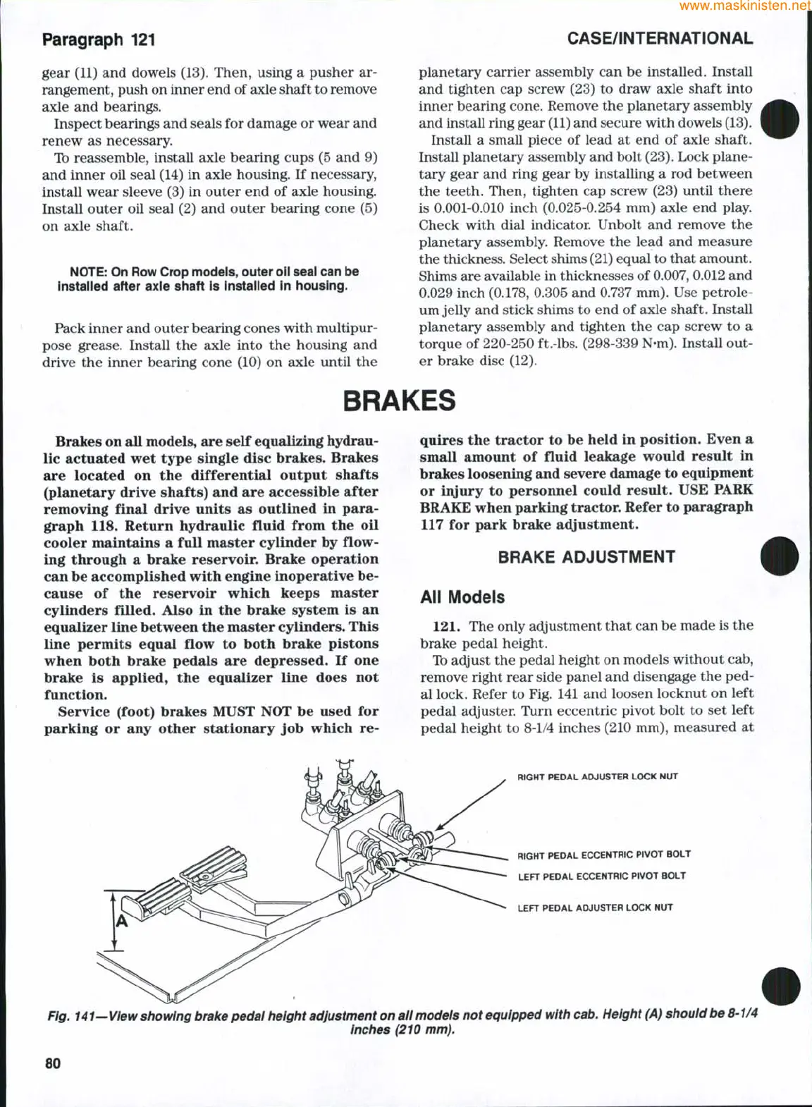
121,
The only adjustment that can be made is the
brake pedal height.
Ib adjust the pedal height on models without cab,
remove right rear side panel and disengage the ped-
al lock. Refer to Fig. 141 and loosen locknut on left
pedal adjuster. Turn eccentric pivot bolt to set left
pedal height to 8-1/4 inches (210 mm), measured at
RIGHT PEDAL ADJUSTER LOCK NUT
RIGHT PEDAL ECCENTRtC PIVOT BOLT
LEFT PEDAL ECCENTRIC PIVOT BOLT
LEFT PEDAL ADJUSTER LOCK NUT
Fig. 141—View showing brake pedai height adjustment on all models not equipped with cab. Height (A) shouid be 8-1/4
inches (210 mm).
80
 Loading...


