SERVICE MANUAL
Paragraphs 125-126
is furnished from the hydraulic pump through the
multiple control valve. From the MCV, the oil is
supplied through a cored passage in the rear
frame to the 1000 rpm output shaft (Models 585,
685 and 885) or lower pto drive shaft (Models 385
and 485) to actuate the pto clutch. Operation of
the pto clutch unit is controlled by a spool type
valve located in the MCV housing.
PTO LINKAGE ADJUSTMENT
NOTE:
Although some checks and adjustments
can be accomplished without removing left rear
wheel,
most mechanics prefer to remove the wheel
to gain woricing room.
All Models
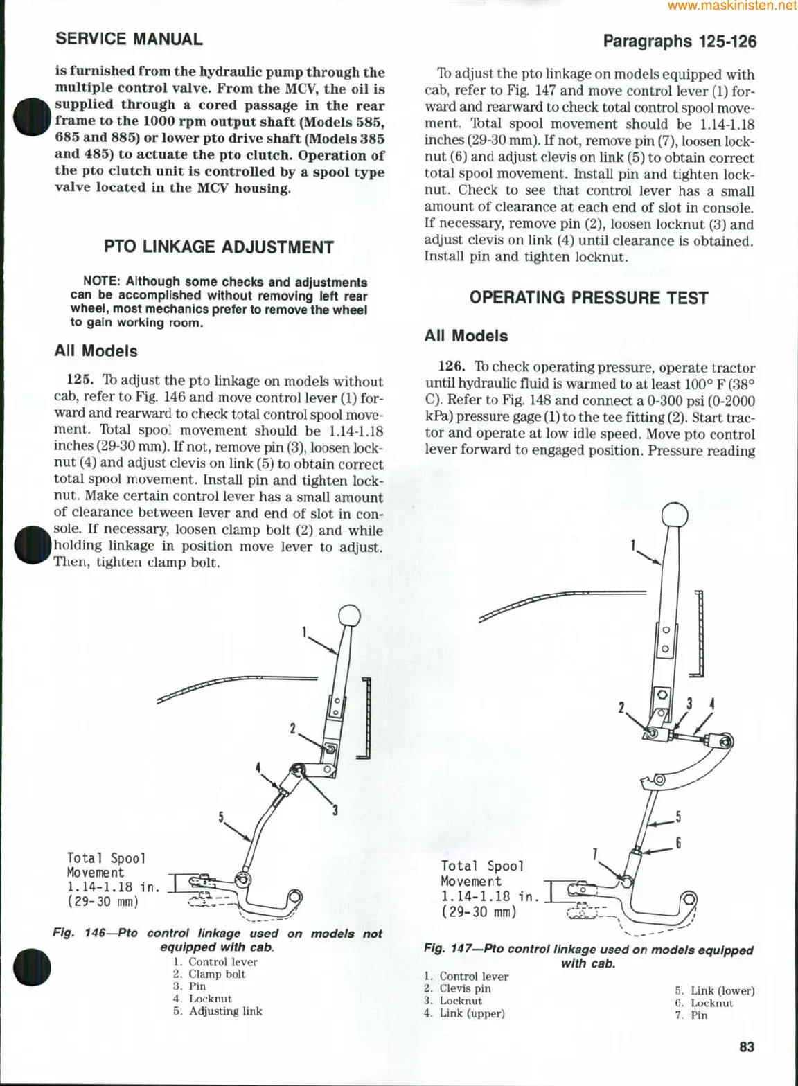
125.
Tb adjust the pto linkage on models without
cab,
refer to Fig. 146 and move control lever (1) for-
ward and rearward to check total control spool move-
ment. Ibtal spool movement should be
1.14-1.18
inches (29-30
mm).
If not, remove pin
(3),
loosen lock-
nut (4) and adjust clevis on link (5) to obtain correct
total spool movement. Install pin and tighten lock-
nut. Make certain control lever has a small amount
of clearance between lever and end of slot in con-
sole.
If necessary, loosen clamp bolt (2) and while
holding linkage in position move lever to adjust.
Then, tighten clamp bolt.
Total Spool
Movement
1.14-1.18
in
(29-30 mm)
Fig.
146—Pto
control linkage used on models not
equipped
with
cab.
1.
Control lever
2.
Clamp bolt
3.
Pin
4.
Locknut
5.
Acyusting link
To
adjust the pto linkage on models equipped with
cab,
refer to Fig. 147 and move control lever (1) for-
ward and rearward to check total control spool move-
ment. T^tal spool movement should be
1.14-1.18
inches (29-30
mm).
If not, remove pin
(7),
loosen lock-
nut (6) and adjust clevis on link (5) to obtain correct
total spool movement. Install pin and tighten lock-
nut. Check to see that control lever has a small
amount of clearance at each end of slot in console.
If necessary, remove pin (2), loosen locknut (3) and
adjust clevis on link (4) until clearance is obtained.
Install pin and tighten locknut.
OPERATING PRESSURE TEST
All Models
126. Tb
check operating pressure, operate tractor
until hydraulic fluid is wanned to at least 100° F (38°
C).
Refer to Fig. 148 and connect a 0-300 psi (0-2000
kPsi)
pressure gage
(1)
to the tee fitting
(2).
Start trac-
tor and operate at low idle speed. Move pto control
lever forward to engaged position. Pressure reading
Total Spool
Movement
1.14-1.18
in.
(29-30
mm)
Fig.
147^Pto
control linkage
used
on
models equipped
with cab.
1.
Control lever
2.
Clevis pin 5. Link (lower)
3.
Locknut 6. Locknut
4.
Link (upper) 7. pin
83