Paragraph 36
CASE/iNTERNATiONAL
coolant. Remove upright muffler and hood. Discon-
nect upper radiator hose from engine. Unbolt and re-
move air cleaner assembly. Remove breather pipe
from rocker arm cover and remove exhaust elbow.
Disconnect, unbolt and remove coolant filter/condi-
tioner, if so equipped. Unbolt and remove exhaust
manifold and coolant manifold. Disconnect and re-
move iryector lines from fuel ir\jectors and ir\jection
pump. Cap or plug all openings to prevent dirt or oth-
er foreign material from entering system. Disconnect
return fuel line and ether starting line. Unbolt and
remove intake manifold. Remove retaining bolts from
rocker arm cover and lift off cover. Unbolt and re-
move rocker arms and shaft assembly, then remove
push rods. Remove head bolts and lift off cylinder
head.
CAUTION:
TKe injector nozzle assemblies pro-
trude slightly through the combustion side of cyl-
inder head. Be extremeiy carefui when removing or
reinstailing cylinder head with injectors instaiied, so
as not to damage injector ends. DO NOT place cyi-
inder head on bench with combustion side down.
Clean all gasket sealing surfaces of cylinder head
and check for cracks or other damage. Using a
straightedge and feeler
gage,
check cylinder head for
warpage. If warpage is more than 0.0047 inch (0.12
mm) resurface cylinder head. A maximum of 0.30
inch (0.77 mm) can be removed from cylinder head.
If cylinder head height is less than 3.8795 inches
(98.54 mm) after head is machined, renew head.
When reinstalling cylinder head, use new head gas-
ket and make sure gasket sealing surfaces of cylin-
der block and head are clean. Use guide studs when
installing head. Tighten cylinder head retaining cap
screws in three steps using the sequence shown in
Fig. 44 or 45. Tighten the cap screws to a torque of
30 ft.-lbs. (41 N-m) in first step, 60 ft.-lbs. (81 N-m)
in second step and 110 ft.-lbs. (149 N-m) in the third
step.
Adjust valve tappet gap as outlined in paragraph
37.
i NOZZLE SLEEVES
Aii Modeis
36.
REMOVE AND REINSTALL. The cylinder
head is fitted with brass iryector nozzle sleeves which
pass through the coolant passages. The nozzle sleeves
are available as service items.
NOTE:
injector nozzie sieeves can be renewed
without removing the cyiinder head. However, if cyi-
inder head is not removed, be sure to drain cooiant
beiow ievei of cylinder head before removing the
sieeves.
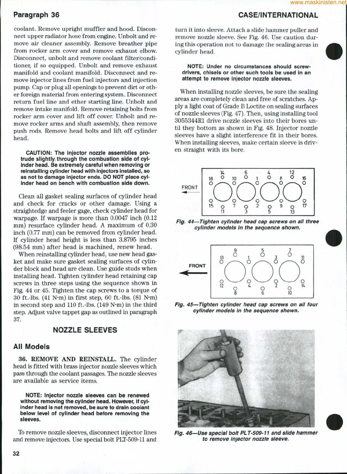
Ib remove nozzle sleeves, disconnect iryector lines
and remove irgectors. Use special bolt
PLT-509-11
and
turn it into sleeve. Attach a slide hammer puller and
remove nozzle sleeve. See Fig. 46. Use caution dur-
ing this operation not to damage the sealing areas in
cylinder head.
NOTE:
Under no circumstances should screw-
drivers, chlseis or other such toois be used in an
attempt to remove injector nozzie sieeves.
When installing nozzle sleeves, be sure the sealing
areas are completely clean and free of scratches. Ap-
ply a light coat of Grade B Loctite on sealing surfaces
of nozzle sleeves (Fig. 47). Then, using installing tool
3055344R1 drive nozzle sleeves into their bores un-
til they bottom as shown in Fig. 48. Ii\jector nozzle
sleeves have a slight interference fit in their bores.
When installing sleeves, make certain sleeve is driv-
en straight with its bore.
FRONT
K 6 4 12
18 O 10 O 1 O e O 16
:o:o:on
o
11
o
13
Fig. 44—Tighten cylinder head cap screws on aii three
cyiinder models in the sequence shown.
FRONT
13
12
9
O
^ N
^- ^
o
8
1
5
O
^—^
V^ ^
O
6
3
2
7
O
^—^
^—^
O
10
11
I
lA
Fig. 45—Tighten cyiinder head cap screws on ail four
cyiinder models In the sequence shown.
r
Fig. 46—Use special bolt PLT-509'11 and slide hammer
to remove Injector nozzie sieeve.
32



 To Next Page