Paragraphs 69-71
A 9-12 psi (62-82 kPa) pressure radiator cap is used
on all models.
FAN
Ail Modeis
69.
The five blade (6 blade with air conditioning)
18 inch (457 mm) diameter fan is attached to the wa-
ter pump shaft. Ib remove the fan, first remove hood
and front side panels. Drain the cooling system and
disconnect upper end of lower radiator hose. Loos-
en adjusting bolts on alternator and loosen the belt.
Unbolt fan shroud and move shroud rearward. Then,
unbolt and remove fan.
Reinstall by reversing the removal procedure. Tight-
en fan mounting bolts to a torque of 8.5 ft.-lbs. (11.5
N-m).
Adjust alternator-fan belt until a pressure of
25 lbs. (Ill N), applied midway between fan pulley
and crankshaft pulley, will deflect belt 3/4 inch (19
mm).
THERMOSTAT
Aii Modeis
70.
All models are equipped with a single ther-
mostat located under the water outlet (at rear of up-
per radiator hose). Thermostat should start to open
at 180° F (84°
C)
and be fully open at 207° F (97° C).
WATER PUMP
Aii Modeis
71.
R&R AND OVERHAUL. Ib remove the water
pump, first remove hood and front side panels. Drain
the cooling system and disconnect upper and lower
radiator hoses. Loosen ac^usting bolts on alternator
and air conditioning compressor, if so equipped, and
remove belts. Unbolt fan shroud and move shroud
rearward, then unbolt and remove fan and pulley. Re-
move mounting bolts and lift out water pump.
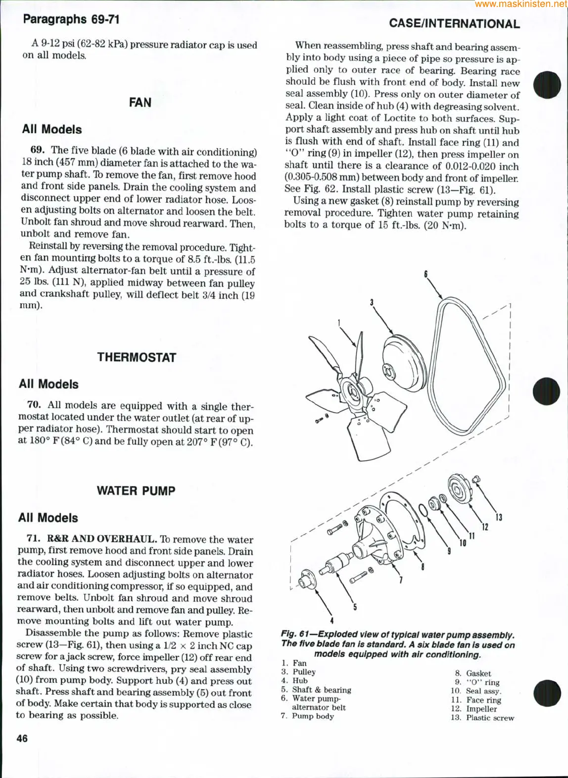
Disassemble the pump as follows: Remove plastic
screw
(13—Fig.
61), then using a 1/2 x 2 inch NC cap
screw for a jack screw, force impeller
(12)
off rear end
of shaft. Using two screwdrivers, pry seal assembly
(10) from pump body. Support hub (4) and press out
shaft. Press shaft and bearing assembly (5) out front
of
body.
Make certain that body is supported as close
to bearing as possible. .
CASE/INTERNATIONAL
When reassembling, press shaft and bearing assem-
bly into body using a piece of pipe so pressure is ap-
plied only to outer race of bearing. Bearing race
should be flush with front end of body. Install new
seal assembly (10). Press only on outer diameter of
seal. Clean inside of hub (4) with degreasing solvent.
Apply a light coat of Loctite to both surfaces. Sup-
port shaft assembly and press hub on shaft until hub
is flush with end of shaft. Install face ring (11) and
**0*'
ring (9) in impeller (12), then press impeller on
shaft until there is a clearance of 0.012-0.020 inch
(0.305-0.508 mm) between body and front of impeller.
See Fig. 62. Install plastic screw (13—Fig. 61).
Using a new gasket (8) reinstall pump by reversing
removal procedure. Tighten water pump retaining
bolts to a torque of 15 ft.-lbs. (20 N-m).
5
Fig. 61—Exploded view of typical water pump assembiy.
The five biade fan is standard. A six biade fan is used on
models equipped with air conditioning.
1.
Fan
3.
Pulley 8. Gasket
4.
Hub 9. **0" ring
5.
Shaft & bearing 10. Seal assy.
6. Water pump- 11. Face ring
alternator belt 12. Impeller
7.
Pump body 13. Plastic screw
46
 Loading...


