SERViCE MANUAL
Paragraphs 19-21
When unit is reassembled, use new gasket, reinstall
transfer gearbox and tighten retaining bolts to a
torque of 90 ft.-lbs. (120
N-m).
Connect electric wire
to solenoid and hydraulic line to gearbox. Use new
gasket (21) and install cover
(22).
Check transmission
oil level and refill with Hy-Tran Plus oil.
Before installing front drive shaft, check the slip
torque of the gearbox clutch as follows: Place trans-
mission in first gear and low range and apply park
brake. Using a torque wrench and special tool CAS-
1876 on end of output shaft, check clutch slip torque.
If unit was assembled with new clutch parts, clutch
should slip at 654 ft.-lbs. (887 N-m). If used clutch
parts were used, clutch should slip at 594 ft.-lbs. (806
N-m).
If slip torque is considerably lower, Belleville
springs may be weak and should be renewed.
Reinstall front drive shaft and drive shaft shield as
outlined in paragraph 16.
TiE RODS AND TOE-iN
Aii Modeis With Front Drive Axie
19.
Ibe-in must be 0-3/16 inch (0-5 mm) and is ad-
justed by turning the threaded studs between steer-
ing cylinder rod and tie rod ends. Both sides must be
adjusted equally.
POWER STEERING SYSTEM
NOTE:
The maintenance of absolute cleanliness
of aii parts is of utmost importance in the operation
and servicing of the hydrostatic steering system. Of
equai importance is the avoidance of nicks or burrs
on any of the woricing parts.
STEERiNG CiRCUITS
Aii Modeis
20.
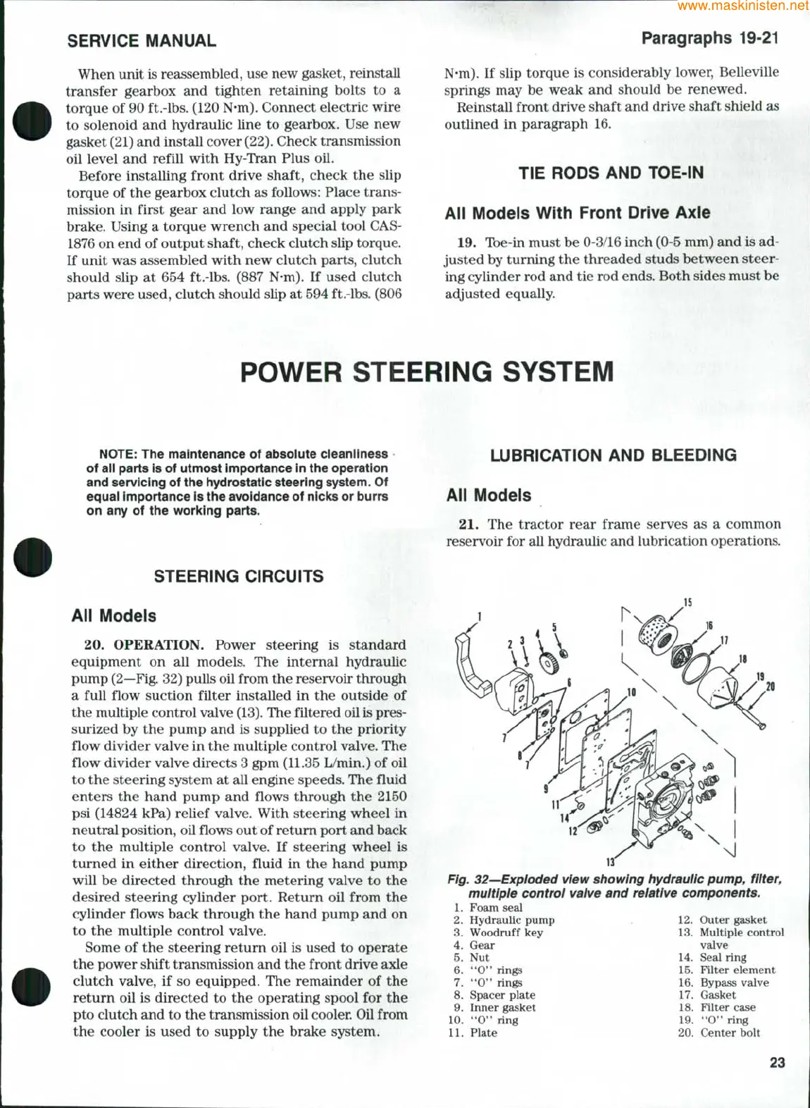
OPERATION. Power steering is standard
equipment on all models. The intemal hydraulic
pump
(2—Fig.
32) pulls oil from the reservoir through
a full flow suction filter installed in the outside of
the multiple control valve
(13).
The filtered oil
is
pres-
surized by the pump and is supplied to the priority
flow divider valve in the multiple control valve. The
flow divider valve directs 3 gpm (11.35 L/min.) of oil
to the steering system at all engine speeds. The fluid
enters the hand pump and flows through the 2150
psi (14824 kPa) relief valve. With steering wheel in
neutral position, oil flows out of retum port and back
to the multiple control valve. If steering wheel is
turned in either direction, fluid in the hand pump
will be directed through the metering valve to the
desired steering cylinder port. Return oil from the
cylinder flows back through the hand pump and on
to the multiple control valve.
Some of the steering return oil is used to operate
the power shift transmission and the front drive axle
clutch valve, if so equipped. The remainder of the
return oil is directed to the operating spool for the
pto clutch and to the transmission oil cooler. Oil from
the cooler is used to supply the brake system.
LUBRiCATiON AND BLEEDiNG
Aii Modeis
21.
The tractor rear frame serves as a common
reservoir for all hydraulic and lubrication operations.
Fig. 32—Expioded view showing hydrauiic pump,
fiiter,
multipie control valve and relative components.
1.
Foam seal
2.
Hydraulic pump . 12
3.
Woodruff key 13
4.
Gear
5.
Nut 14
6. **0" rings
7.
**0" rings
8. Spacer plate 17
9. Inner gasket 18
10.
"0" ring 19
11.
Plate
Outer gasket
Multiple control
valve
Seal ring
15.
Filter element
16.
Bypass valve
Gasket
Filter case
"0"
ring
20.
Center bolt
23