Paragraphs 22-23
CASE/iNTERNATiONAL
The filter element (15—Fig. 32) should be renewed
after 20 hours, 200 hours and then every 800 hours
of operation. Hydraulic fluid should be drained and
new fluid installed every 800 hours of operation or
once a year, whichever occurs first. Only Hy-Tran
Plus fluid should be used and level should be main-
tained at full mark on dipstick. Refill capacity is 36
U.S.
quarts (34 L) on tractors without front drive axle
and 38.6 U.S. quarts (36.5 L) on tractors with front
drive axle.
Whenever power steering lines have been discon-
nected or the fluid changed, start engine and cycle
power steering system from stop to stop several times
to bleed air from system. Then, check and if neces-
sary, add transmission fluid.
HYDROSTATiC STEERiNG TESTS
Ail Modeis
iMPORTANT: Before any hydrauiic tests are made,
transmission oil in the tractor must be warmed to
a temperature of at ieast 100'' F (38*" C).
22.
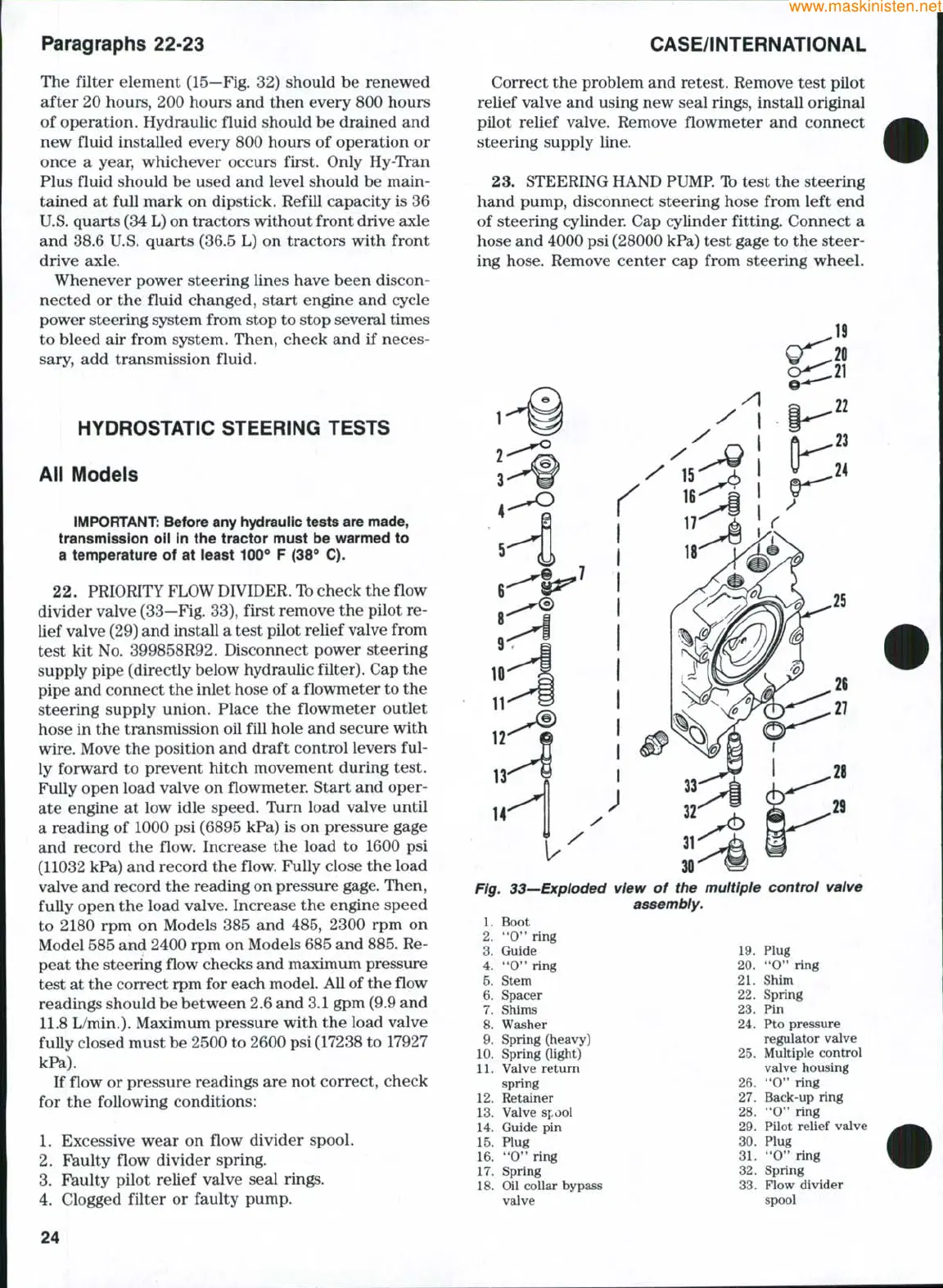
PRIORITY FLOW DIVIDER. Ib check the flow
divider valve (33—Fig. 33), first remove the pilot re-
lief valve (29) and install a test pilot relief valve from
test kit No. 399858R92. Disconnect power steering
supply pipe (directly below hydraulic filter). Cap the
pipe and connect the inlet hose of a flowmeter to the
steering supply union. Place the flowmeter outlet
hose in the transmission oil fill hole and secure with
wire.
Move the position and draft control levers ful-
ly forward to prevent hitch movement during test.
Fully open load valve on flowmeter. Start and oper-
ate engine at low idle speed. Turn load valve until
a reading of 1000 psi (6895 kPa) is on pressure gage
and record the flow. Increase the load to 1600 psi
(11032 kPa) and record the flow. Fully close the load
valve and record the reading on pressure gage. Then,
fully open the load valve. Increase the engine speed
to 2180 rpm on Models 385 and 485, 2300 rpm on
Model 585 and 2400 rpm on Models 685 and 885. Re-
peat the steering flow checks and maximum pressure
test at the correct rpm for each model. All of the flow
readings should be between 2.6 and 3.1 gpm (9.9 and
11.8 L/min.). Maximum pressure with the load valve
fully closed must be 2500 to 2600 psi (17238 to 17927
kPa).
If flow or pressure readings are not correct, check
for the following conditions:
1.
Excessive wear on flow divider spool.
2.
Faulty flow divider spring.
3.
Faulty pilot relief valve seal rings.
4.
Clogged filter or faulty pump.
Correct the problem and retest. Remove test pilot
relief valve and using new seal rings, install original
pilot relief valve. Remove flowmeter and connect
steering supply line.
23.
STEERING HAND PUMP. Ib test the steering
hand pump, disconnect steering hose from left end
of steering cylinder. Cap cylinder fitting. Connect a
hose and 4000 psi (28000 kPa) test gage to the steer-
ing hose. Remove center cap from steering wheel.
14
Fig, 33—Exploded view of the muitipie controi valve
assembly.
1.
Boot
2.
"O" ring
3.
Guide
4.
*'O" ring
5.
Stem
6. Spacer
7.
Shims
8. Washer
9. Spring (heavy)
10.
Spring (light)
11.
Valve return
spring
12.
Retainer
13.
Valve spool
14.
Guide pin
15.
Plug
16.
**0" ring
17.
Spring
18.
Oil collar bypass
valve
19.
Plug
20.
'*0" ring
21.
Shim
22.
Spring
23.
Pin
24.
Pto pressure
regulator valve
25.
Multiple control
valve housing
26.
*'O" ring
27.
Back-up ring
28.
"O'* ring
29.
Pilot relief valve
30.
Plug
31.
**0" ring
32.
Spring
33.
Flow divider
spool
24