Paragraph 104
CASE/iNTERNATiONAL
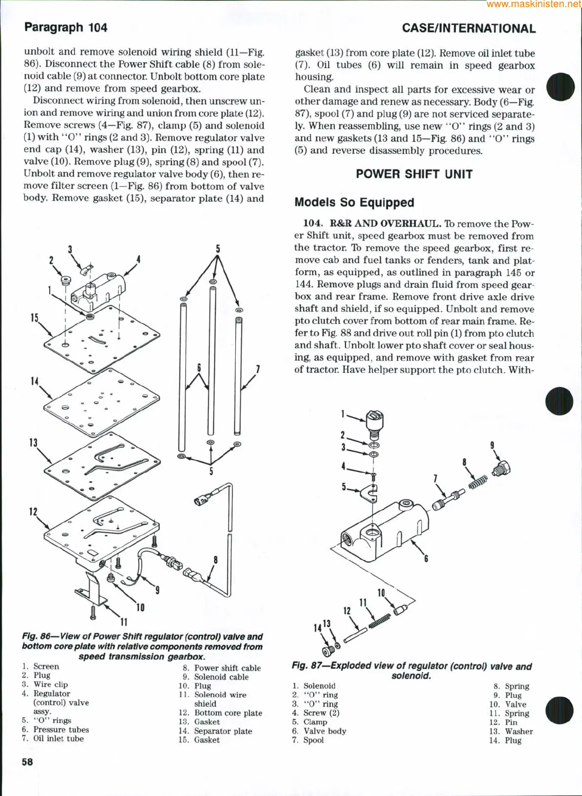
unbolt and remove solenoid wiring shield (11—Fig.
86).
Disconnect the Power Shift cable (8) from sole-
noid cable (9) at connector Unbolt bottom core plate
(12) and remove from speed gearbox.
Disconnect wiring from solenoid, then unscrew un-
ion and remove wiring and union from core plate (12).
Remove screws (4—Fig. 87), clamp (5) and solenoid
(1) with
"0**
rings (2 and
3).
Remove regulator valve
end cap (14), washer (13), pin (12), spring (11) and
valve (10). Remove plug (9), spring (8) and spool (7).
Unbolt and remove regulator valve body
(6),
then re-
move filter screen (1—Fig. 86) from bottom of valve
body. Remove gasket (15), separator plate (14) and
Fig. 86—
View
of Power Shift reguiator
(controi) valve
and
bottom
core
plate
with relative components removed from
speed transmission gearbox.
1.
Screen 8. Power shift cable
2.
Plug 9.
3.
Wire clip 10.
4.
Regulator U.
(control) valve
assy. 12.
"0"
rings 13.
Pressure tubes 14.
5
6
7.
Oil inlet tube
Solenoid cable
Plug
Solenoid wire
shield
Bottom core plate
Gasket
Separator plate
gasket (13) from core plate
(12).
Remove oil inlet tube
(7).
Oil tubes (6) will remain in speed gearbox
housing.
Clean and inspect all parts for excessive wear or
other damage and renew as necessary. Body (6—Fig.
87),
spool (7) and plug (9) are not serviced separate-
ly. When reassembling, use new **0'' rings (2 and 3)
and new gaskets (13 and 15—Fig. 86) and '*0" rings
(5) and reverse disassembly procedures,
POWER SHiFT UNiT
Modeis So Equipped
104.
R&R AND OVERHAUL. Ib remove the Pow-
er Shift unit, speed gearbox must be removed from
the tractor. Ib remove the speed gearbox, first re-
move cab and fuel tanks or fenders, tank and plat-
form, as equipped, as outlined in paragraph 145 or
144.
Remove plugs and drain fluid from speed gear-
box and rear frame. Remove front drive axle drive
shaft and shield, if so equipped. Unbolt and remove
pto clutch cover from bottom of rear main frame. Re-
fer to
Fig.
88 and drive out roll pin
(1)
from pto clutch
and shaft. Unbolt lower pto shaft cover or seal hous-
ing, as equipped, and remove with gasket from rear
of tractor. Have helper support the pto clutch. With-
15.
Gasket
Fig. 87—Expioded view of regulator (control) valve and
solenoid.
1.
Solenoid 8. Spring
2.
**0'*
ring 9. Plug
3.
*'O'' ring 10. Valve
4.
Screw (2) 11. Spring
5.
Clamp 12, Pin
6. Valve body 13. Washer
7.
Spool 14. Plug
58



 To Next Page