SERViCE MANUAL
VALVES AND SEATS
Aii Modeis
37.
Intake and exhaust valves are not interchange-
able.
Intake valves seat directly in the cylinder head
and exhaust valves seat on renewable seat inserts.
Inserts are available in oversizes of 0.006 inch (0.15
mm) and 0.016 inch (0.40 mm). Valve seat angle for
both intake and exhaust valves is 44 degrees. Valve
face angle for both intake and exhaust valves is 45
degrees. This provides a
1
degree interference angle
between valves and seats. Valve stem seals are used
on all valves and valve rotators are used on all valves.
When removing valve seat inserts, use the proper
seat puller or use a pre-cup puller and expanding
screw. DO NOT attempt to drive a chisel or similar
tool under insert as the counterbore will be damaged.
Freeze new valve seat inserts to a temperature of
-76° F (-60° C) before installing.
Check the valves and seats against the following
specifications:
Intake
Valve face angle 45°
Valve seat angle 44°
Stem diameter 0.3920-0.3924 in.
(9.957-9.967 mm)
Stem to guide diametral
clearance 0.0016-0.0025 in.
(0.041-0.064 mm)
Seat width 0.060-0.070 in.
(1.52-1.78 mm)
Valve tappet gap (warm) 0.012 in.
(0.304 mm)
Valve recession from
face of cylinder head 0.040-0.050 in.
(1.02-1.27 mm)
Exhaust
Valve face angle 45°
Valve seat angle 44°
Stem diameter 0.3912-0.3915 in.
(9.936-9.945 mm)
SEAUNG SURFACES
Paragraph 37
Stem to guide diametral
clearance 0.0025-0.0033 in.
(0.064-0.084 mm)
Seat width 0.060-0.070 in.
(1.52-1.78 mm)
Valve tappet gap (warm) 0.012 in.
(0.304 mm)
Valve recession from
face of cylinder head 0.047-0.060 in.
(1.19-1.52 mm)
CAUTION:
Due to ciose clearance between valves
and pistons, severe damage can result from insert-
ing feeier gage between vaive stem and vaive lever
(rocker arm) with engine running. DO NOT attempt
to adjust tappet gap with engine running.
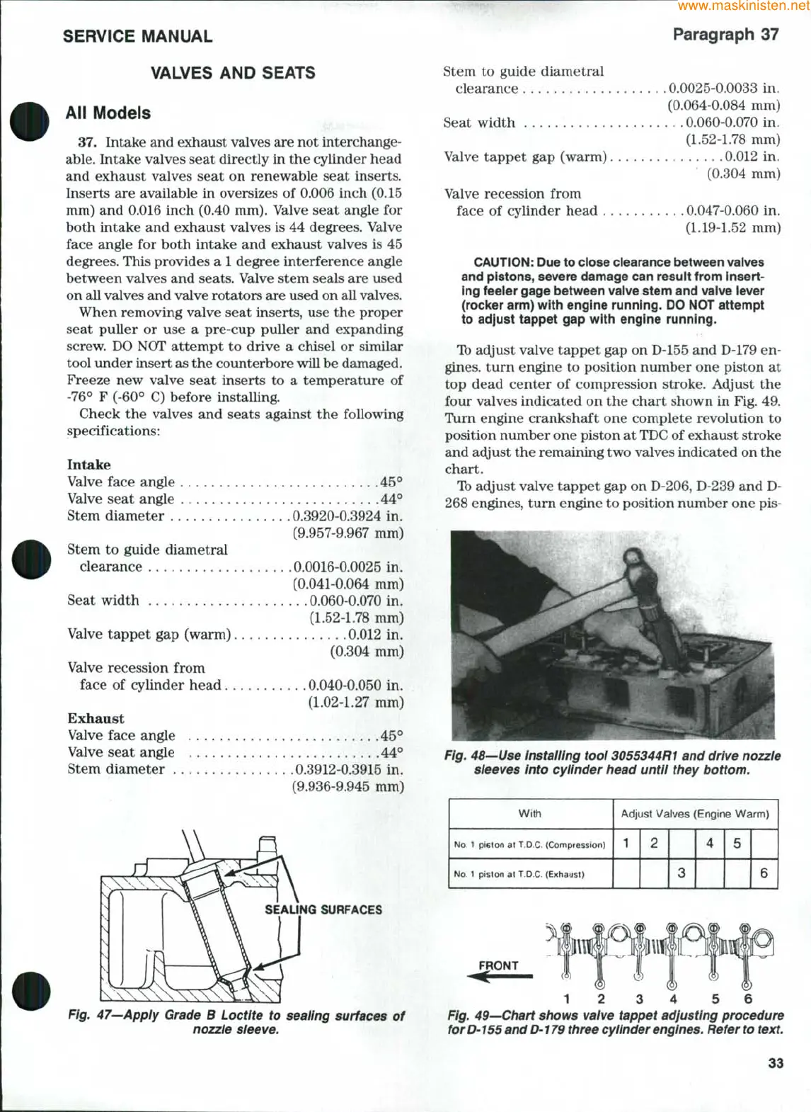
Ib adjust valve tappet gap on D-155 and D-179 en-
gines,
turn engine to position number one piston at
top dead center of compression stroke. Adjust the
four valves indicated on the chart shown in Fig. 49.
Turn engine crankshaft one complete revolution to
position number one piston at
TDC
of exhaust stroke
and acijust the remaining two valves indicated on the
chart.
Ib adjust valve tappet gap on D-206, D-239 and D-
268 engines, turn engine to position number one pis-
Fig. 48—Use installing tooi 3055344R1 and drive nozzle
sleeves into cyiinder head until they bottom.
With
No.
1 pi6ton at T.D.C- (Compression)
No.
1 piston at T.O.C. (Exhaust)
Adjust Valves (Engine Warm)
1
2
3
4
5
6
Fig. 47—Apply Grade B Loctite to sealing surfaces of
nozzle sleeve.
12 3 4 5 6
Fig. 49—Chart shows valve tappet adjusting procedure
for D'
155
and D-179 three cylinder
engines.
Refer
to
text.
33
 Loading...


