Paragraphs 1-2
CASE/INTERNATIONAL
FRONT AXLE (TWO-WHEEL DRIVE)
FRONT WHEEL BEARING
All Models
1.
Refer to Figs.
1
and 2 for typical wheel hub and
bearing assemblies.
The tapered inner and outer roller bearings are not
interchangeable. Clean and inspect bearing cups (3
and 5) and cones (2 and 6) and renew as necessary.
NOTE:
On adjustable axle hubs, if wear ring (12)
is excessiveiy worn, renew wear ring.
Install inner seal
(1)
on spindle and coat lips of seal
with grease. Pack bearings and fill hub cavity with
No.
2 lithium gi^ease. Install inner bearing cone (2).
Install hub assembly (4), outer bearing cone (6),
washer (7) and nut
(9).
Adyust wheel bearing preload
as follows: Tighten nut to a torque of 70 ft
.-lbs.
(95
N*m) while rotating the hub. Then, loosen nut and
retorque to 50 ft.-lbs. (68 N-m) on Models 385, 485
and 585 with standard axles or 25 ft.-lbs. (34 N*m)
on Models 385, 485 and 585 equipped with heavy
duty axles and all Model 685 and 885 tractors. Then,
11
13
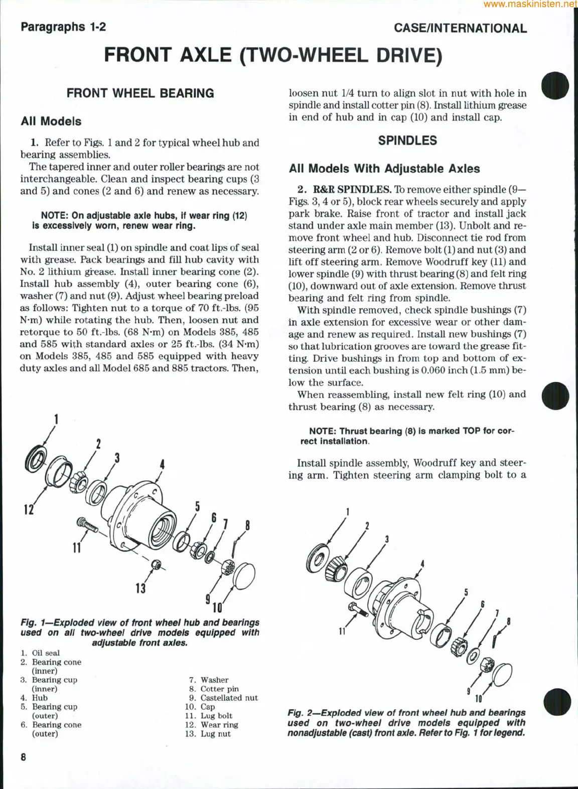
Fig. 1—Exploded view of front wheel hub and bearings
used on all two-wheel drive models equipped with
adjustable front axles.
1.
Oil seal
2.
Bearing cone
(inner)
3.
Bearing cup 7. Washer
(inner) 8. Cotter pin
4.
Hub 9. Castellated nut
5.
Bearing cup 10. Cap
(outer) 11. Lug bolt
Bearing cone 12. Wear ring
loosen nut 1/4 turn to align slot in nut with hole in
spindle and install cotter pin
(8).
Install lithium grease
in end of hub and in cap (10) and install cap.
SPINDLES
All Models With Adjustable Axles
2.
R&R SPINDLES. Ib remove either spindle
(9—
Figs.
3, 4 or
5),
block rear wheels securely and apply
park brake. Raise front of tractor and install jack
stand under axle main member (13). Unbolt and re-
move front wheel and hub. Disconnect tie rod from
steering arm (2 or
6).
Remove bolt
(1)
and nut (3) and
lift off steering arm. Remove Woodruff key (11) and
lower spindle (9) with thrust bearing (8) and felt ring
(10),
downward out of axle extension. Remove thrust
bearing and felt ring from spindle.
With spindle removed, check spindle bushings (7)
in axle extension for excessive wear or other dam-
age and renew as required. Install new bushings (7)
so that lubrication grooves are toward the grease fit-
ting. Drive bushings in from top and bottom of ex-
tension until each bushing is 0.060 inch (1.5 mm) be-
low the surface.
When reassembling, install new felt ring (10) and
thrust bearing (8) as necessary.
NOTE:
Thrust bearing (8) is marked TOP for cor-
rect instaiiation.
Install spindle assembly. Woodruff key and steer-
ing arm. Tighten steering arm clamping bolt to a
(outer)
13.
Lug nut
Fig, 2—Exploded view of front wheel hub and bearings
used on two-wheel drive models equipped with
nonadjustable
(cast) front
axle.
Refer to
Fig.
1
for
legend.
 Loading...


