SERViCE MANUAL
Paragraphs 79-*80
Lucas A115-45
79.
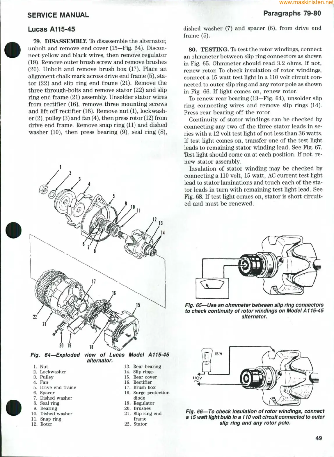
DISASSEMBLE. Ib disassemble the altemator,
unbolt and remove end cover (15—Fig. 64). Discon-
nect yellow and black wires, then remove regulator
(19).
Remove outer brush screw and remove brushes
(20).
Unbolt and remove brush box (17). Place an
alignment chalk mark across drive end frame
(5),
sta-
tor (22) and slip ring end frame (21). Remove the
three through-bolts and remove stator (22) and slip
ring end frame (21) assembly. Unsolder stator wires
from rectifier (16), remove three mounting screws
and lift off rectifier (16). Remove nut (1), lockwash-
er
(2),
pulley (3) and fan
(4),
then press rotor
(12)
from
drive end frame. Remove snap ring (11) and dished
washer (10), then press bearing (9), seal ring (8),
22
21
20
19
Fig. 64—Exploded
1.
Nut
2.
Lockwasher
3.
Pulley
4.
Fan
5.
Drive end frame
6. Spacer
7.
Dished washer
8. Seal ring
9. Bearing
10.
Dished washer
IL Snap ring
12.
Rotor
view of Lucas Modei All5-45
alternator.
13.
Rear bearing
14.
Slip rings
15.
Rear cover
16.
Rectifier
17.
Brush box
18.
Surge protection
diode
19.
Regulator
20.
Brushes
21.
Slip ring end
frame
22.
Stator
dished washer (7) and spacer (6), from drive end
frame (5).
80.
TESTING. Ib test the rotor windings, connect
an ohmmeter between slip ring connectors as shown
in Fig. 65. Ohmmeter should read 3.2 ohms. If not,
renew rotor. Ib check insulation of rotor windings,
connect a 15 watt test light in a 110 volt circuit con-
nected to outer slip ring and any rotor pole as shown
in Fig. 66. If light comes on, renew rotor.
Ib renew rear bearing (13—Fig. 64), unsolder slip
ring connecting wires and remove slip rings (14).
Press rear bearing off the rotor
Continuity of stator windings can be checked by
connecting any two of the three stator leads in se-
ries with a 12 volt test light of not less than 36 watts.
If test light comes on, transfer one of the test light
leads to remaining stator winding lead. See Fig. 67.
Ifest light should come on at each position. If not, re-
new stator assembly.
Insulation of stator winding may be checked by
connecting a 110 volt, 15 watt, AC current test light
lead to stator laminations and touch each of the sta-
tor leads in turn with remaining test light lead. See
Fig. 68. If test light comes on, stator is short circuit-
ed and must be renewed.
Fig. 65—Use an ohmmeter between slip ring connectors
to check continuity of rotor windings on Modei A115-45
aiternator.
Fig. 66—To check insuiation of rotor windings, connect
a 15 watt iight
bulb
in a 110 volt
circuit
connected
to
outer
siip ring and any rotor poie.
49