SERViCE MANUAL
Paragraphs 88-91
88.
FIELD COIL
TEST.
Field coil insulation can be
checked using 110 volt,
15
watt, AC current test light
connected as shown in Fig. 76. Brushes must not
touch field housing and power terminal insulation
must not aUow voltage to short to housing. If test light
comes on and brushes are clear of housing and pow-
er terminal insulation is good, there is a short be-
tween field coils (20-Fig. 74) and field housing (18).
Repair or renew as necessary.
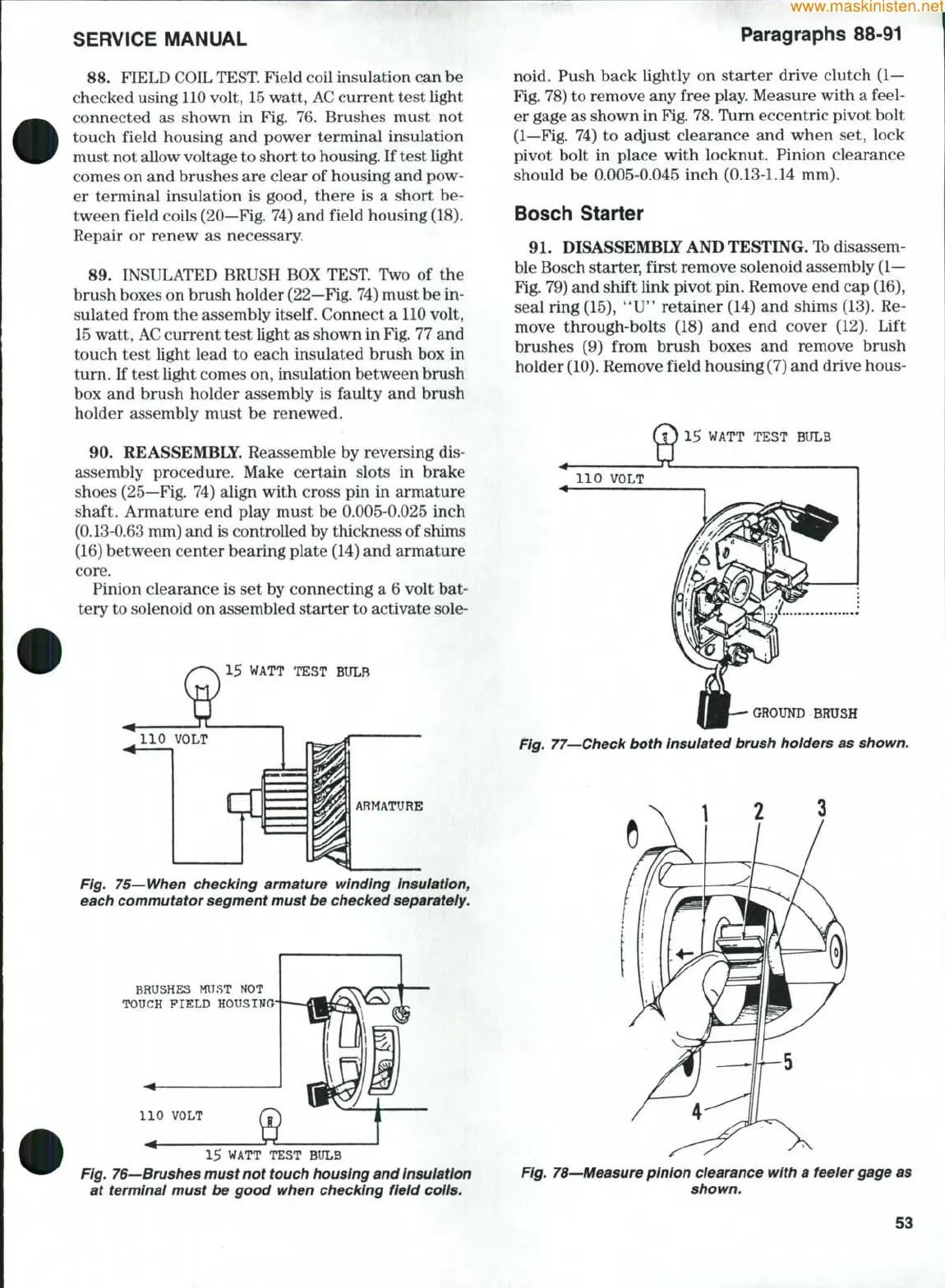
89.
INSULATED BRUSH BOX TEST Two of the
brush boxes on brush holder
(22—Fig.
74) must be in-
sulated from the assembly
itself.
Connect a 110 volt,
15
watt,
AC
current test light as shown in
Fig.
77 and
touch test light lead to each insulated brush box in
tum. If test light comes on, insulation between brush
box and brush holder assembly is faulty and brush
holder assembly must be renewed.
90.
REASSEMBLY. Reassemble by reversing dis-
assembly procedure. Make certain slots in brake
shoes (25—Fig. 74) align with cross pin in armature
shaft. Armature end play must be 0.005-0.025 inch
(0.13-0.63 mm) and is controlled by thickness of shims
(16) between center bearing plate (14) and armature
core.
Pinion clearance is set by connecting a 6 volt bat-
tery to solenoid on assembled starter to activate sole-
15 WATT TEST BULB
110 VOLT
Lfl
Fig. 75—When checking armature winding insuiation,
each commutator segment must be checked separateiy.
BRUSHES MUST NOT
TOUCH FIELD HOUSING
110 VOLT
15 WATT TEST BULB
Fig. 76—Brushes must not touch housing and insuiation
at terminal must be good when checking fieid coils.
noid. Push back lightly on starter drive clutch
(1—
Fig. 78) to remove any free play. Measure with a feel-
er gage as shown in Fig.
78.
Turn eccentric pivot bolt
(1—Fig. 74) to adjust clearance and when set, lock
pivot bolt in place with locknut. Pinion clearance
should be 0.005-0.045 inch (0.13-1.14 mm).
Bosch Starter
91.
DISASSEMBLE AND TESTING. Ib disassem-
ble Bosch starter, first remove solenoid assembly
(1—
Fig. 79) and shift link pivot pin. Remove end cap (16),
seal ring (15), **U*' retainer (14) and shims (13). Re-
move through-bolts (18) and end cover (12). Lift
brushes (9) from brush boxes and remove brush
holder
(10).
Remove field housing (7) and drive hous-
15 WATT TEST BULB
•GROUND BRUSH
Fig. 77—Check both insulated brush holders as shown.
Fig. 78—Measure pinion clearance with a feeier gage as
shown.
53
 Loading...


