Paragraphs 134-135
CASE/INTERNATIONAL
When hitch links have stopped lowering, loosen lock-
nut and turn adjusting screw until it just touches the
stop plate in the hydraulic lift housing. See Fig. 158.
Tighten locknut.
134.
DRAFT CONTROL LEVER. Start engine and
operate at 1000 rpm. Move position control lever into
full lower position and the raise rate lever rearward
into the fast raise position. Move draft control lever
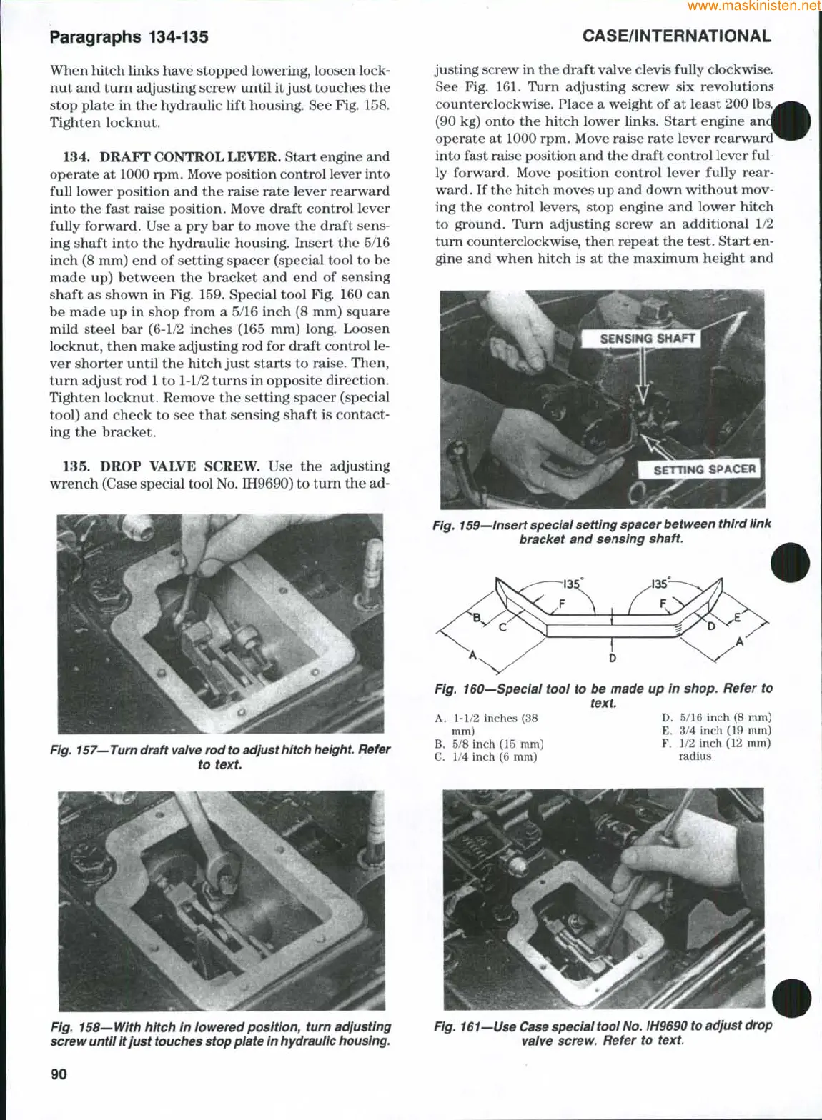
fully forward. Use a pry bar to move the draft sens-
ing shaft into the hydraulic housing. Insert the 5/16
inch (8 mm) end of setting spacer (special tool to be
made up) between the bracket and end of sensing
shaft as shown in Fig. 159. Special tool Fig. 160 can
be made up in shop from a 5/16 inch (8 mm) square
mild steel bar (6-1/2 inches (165 mm) long. Loosen
locknut, then make adjusting rod for draft control le-
ver shorter until the hitch just starts to raise. Then,
turn adjust rod
1
to 1-1/2 turns in opposite direction.
Tighten locknut. Remove the setting spacer (special
tool) and check to see that sensing shaft is contact-
ing the bracket.
135.
DROP VALVE SCREW. Use the adjusting
wrench (Case special tool
No.
IH9690) to turn the ad-
justing screw in the draft valve clevis fuUy clockwise.
See Fig. 161. Turn adjusting screw six revolutions
counterclockwise. Place a weight of at least 200
(90 kg) onto the hitch lower links. Start engine
operate at 1000 rpm. Move raise rate lever rearward
into fast raise position and the draft control lever ful-
ly forward. Move position control lever fully rear-
ward. If the hitch moves up and down without mov-
ing the control levers, stop engine and lower hitch
to ground. Turn adjusting screw an additional 1/2
turn counterclockwise, then repeat the test. Start en-
gine and when hitch is at the maximum height and
Fig.
159—Insert
special setting spacer between third
link
bracket and sensing shaft.
Fig.
157—Turn
draft
valve
rod
to adjust hitch
height.
Refer
to
text.
Fig. 160—Special tool to be made up in shop. Refer to
text.
A. 1-1/2 inches (38 D. 5/16 inch (8 mm)
mm) E. 3/4 inch (19 mm)
B.
5/8 inch (15 mm) F. 1/2 inch (12 mm)
C. 1/4 inch (6 mm) radius
Fig. 158—With hitch In lowered position, turn adjusting
screw until It just
touches
stop plate In
hydraulic
housing.
Fig.
161—Use Case
special tool
No.
IH9690
to
adjust
drop
valve screw. Refer to
text.
90
 Loading...


