Paragraphs 92-97
CASE/iNTERNATiONAL
ing (3). Remove starter drive (23) and center bear-
ing plate (5). Inspect bushings (2, 4, 11 and 22) for
excessive wear or other damage. Renew as required.
Soak new bushings in oil for 24 hours prior to instal-
lation. Inspect brushes and springs and renew if ex-
cessively wom or damaged. Brush minimum length
is 0.335 inch (8.5 mm). The new service brushes are
attached with small bolts instead of solder. Replace-
ment brush service package (19) consists of four
brushes and attaching bolts.
92.
ARMATURE. Inspect armature commutator
for wear, roughness or pitting. Commutator can be
trued in a lathe. Minimum commutator diameter is
1.67 inches (42.5 mm). The mica insulation between
segments can be undercut to a depth of 0.001 inch
(0.025 mm). After undercutting, polish commutator
with nonconductive emery cloth.
93.
ARMATURE INSULATION
TEST.
Armature in-
sulation can be checked by using a 110 volt, 15 watt
test light connected as shown in Fig. 75. Ibuch each
commutator segment in turn with test light lead. If
test light comes on at any segment, windings are
shorted and armature must be repaired or renewed.
18
Fig.
1/
2
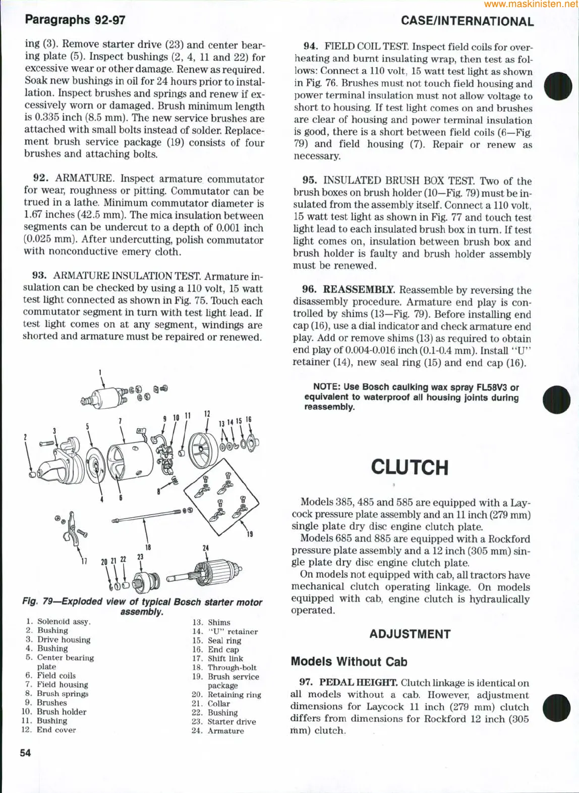
79—Expioded
1.
Solenoid assy.
2.
Bushing
3.
Drive housing
4.
Bushing
5.
Center bearing
plate
6. Field coils
7.
Field housing
8. Brush springs
9. Brushes
10.
Brush holder
11.
Bushing
12.
3nd cover
view of typical Bosch starter motor
assembiy.
13.
Shims
14.
"U" retainer
15.
Seal ring
16.
End cap
17.
Shift link
18.
Through-bolt
19.
Brush service
package
20.
Retaining ring
21.
Collar
22.
Bushing
23.
Starter drive
24.
Armature
94.
FIELD COIL TEST Inspect field coils for over-
heating and burnt insulating wrap, then test as fol-
lows:
Connect a 110 volt, 15 watt test light as shown
in Fig. 76. Brushes must not touch field housing and
power terminal insulation must not allow voltage to
short to housing. If test light comes on and brushes
are clear of housing and power terminal insulation
is good, there is a short between field coils (6—Fig.
79) and field housing (7). Repair or renew as
necessary.
95.
INSULATED BRUSH BOX TEST Two of the
brush boxes on brush holder
(10—Fig.
79) must be in-
sulated from the assembly
itself.
Connect a 110 volt,
15 watt test light as shown in Fig. 77 and touch test
light lead to each insulated brush box in turn. If test
light comes on, insulation between brush box and
brush holder is faulty and brush holder assembly
must be renewed.
96.
REASSEMBLE. Reassemble by reversing the
disassembly procedure. Armature end play is con-
trolled by shims (13—Fig. 79). Before installing end
cap
(16),
use a dial indicator and check armature end
play. Add or remove shims (13) as required to obtain
end play of 0.004-0.016 inch (0.1-0.4 mm). Install *'U'*
retainer (14), new seal ring (15) and end cap (16).
NOTE:
Use Bosch caulking wax spray FL58V3 or
equivalent to waterproof all housing joints during
reassembiy.
CLUTCH
Models
385,
485 and 585 are equipped with a Lay-
cock pressure plate assembly and an
11
inch (279 mm)
single plate dry disc engine clutch plate.
Models 685 and 885 are equipped with a Rockford
pressure plate assembly and a 12 inch (305 mm) sin-
gle plate dry disc engine clutch plate.
On models not equipped with cab, all tractors have
mechanical clutch operating linkage. On models
equipped with cab, engine clutch is hydraulically
operated.
ADJUSTMENT
Modeis Without Cab
97.
PEDAL
HEIGHT.
Clutch Unkage is identical on
all models without a cab. However, adjustment
dimensions for Laycock 11 inch (279 mm) clutch
differs from dimensions for Rockford 12 inch (305
mm) clutch.
54
 Loading...


