Paragraph 109
CASE/iNTERNATIONAL
to select forward direction. Record pressure gage
reading. Move control to select reverse direction and
record gage reading. Stop engine. Pressure readings
in both forward and reverse must be 300-320 psi
(2070-2210 kPa). A low reading for one direction only
would indicate damaged piston seal rings for that
clutch. If readings are low in both forward and re-
verse, add shims (3—Fig. 100) in regulator as re-
quired. Adding one shim will increase pressure by 20-
30 psi (138-207 kP^). If a total of more than four shims
are required, renew spring (5).
FORWARD-REVERSE UNiT
Modeis So Equipped
109.
R&R AND OVERHAUL. To remove the
Forward-Reverse unit, speed gearbox must be re-
moved from tractor. Ib remove the speed gearbox,
first remove cab and fuel tanks or fenders, tank and
platform, as equipped, as outlined in paragraph 145
or 144. Remove plugs and drain fluid from speed
gearbox and rear frame. Remove front drive axle
drive shaft and shield if so equipped. Unbolt and re-
move pto clutch cover from bottom of rear main
frame. Drive roll pin from pto clutch and shaft. Un-
bolt lower pto shaft cover or seal housing, as
equipped, and remove with gasket from rear of trac-
tor. Have helper support the pto clutch. Withdraw
lower pto shaft and remove pto clutch. Unbolt and
remove bottom core plate and regulator valve as out-
lined in paragraph 107. Remove oil inlet tube from
Forward-Reverse clutch housing. Disconnect lst-2nd
and 3rd-4th selector rods from gear selector levers.
Disconnect all interfering hydraulic lines and wiring.
Using a sling and hoist
(Fig.
102), lift off steering sup-
port assembly. Remove right and left brake pipes. Re-
move steering supply and return pipes and oil cool-
er supply and return pipes. Plug or cap all openings
immediately to prevent foreign material from enter-
ing systems. Disconnect and remove the Forward-
Reverse lockout mechanism from speed selector
cover.
Place special tool (Churchill #MS 2700) or equiva-
lent, under tractor. See Fig. 89A. Adjust splitting tool
to support tractor under speed gearbox and rear main
frame. Place wooden wedges between front axle and
front support to prevent tipping. Unbolt range sec-
tion (rear frame) from speed gearbox. After making
certain that all wires and hydraulic lines are discon-
nected, roll engine and speed gearbox assembly for-
ward from range section.
Attach a sling and hoist to speed gearbox and block
up securely under engine oil pan. Unbolt clutch hous-
ing from engine, then separate speed gearbox from
engine. If available, attach speed gearbox assembly
in a transmission stand.
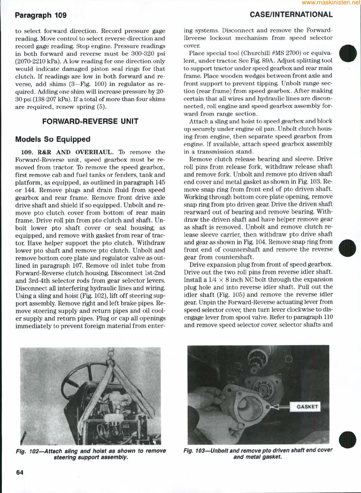
Remove clutch release bearing and sleeve. Drive
roll pins from release fork, withdraw release shaft
and remove fork. Unbolt and remove pto driven shaft
end cover and metal gasket as shown in Fig. 103. Re-
move snap ring from front end of pto driven shaft.
Working through bottom core plate opening, remove
snap ring from pto driven gear. Drive the driven shaft
rearward out of bearing and remove bearing. With-
draw the driven shaft and have helper remove gear
as shaft is removed. Unbolt and remove clutch re-
lease sleeve carrier, then withdraw pto drive shaft
and gear as shown in
Fig.
104. Remove snap ring from
front end of countershaft and remove the reverse
gear from countershaft.
Drive expansion plug from front of speed gearbox.
Drive out the two roll pins from reverse idler shaft.
Install a 1/4 X 8 inch NC bolt through the expansion
plug hole and into reverse idler shaft. Pull out the
idler shaft (Fig. 105) and remove the reverse idler
gear. Unpin the Forward-Reverse actuating lever from
speed selector cover, then tum lever clockwise to dis-
engage lever from spool valve. Refer to paragraph 110
and remove speed selector cover, selector shafts and
Fig. 102—Attach siing and hoist as shown to remove
steering support assembly.
Fig. 103—Unbolt and remove pto driven shaft end cover
and metal gasket.
64
 Loading...


