Paragraph 130
CASE/INTERNATIONAL
that system is completely free of air. Remove cab or
fenders, fuel tank and seal platform, as equipped, as
outlined in paragraph 145 or 144.
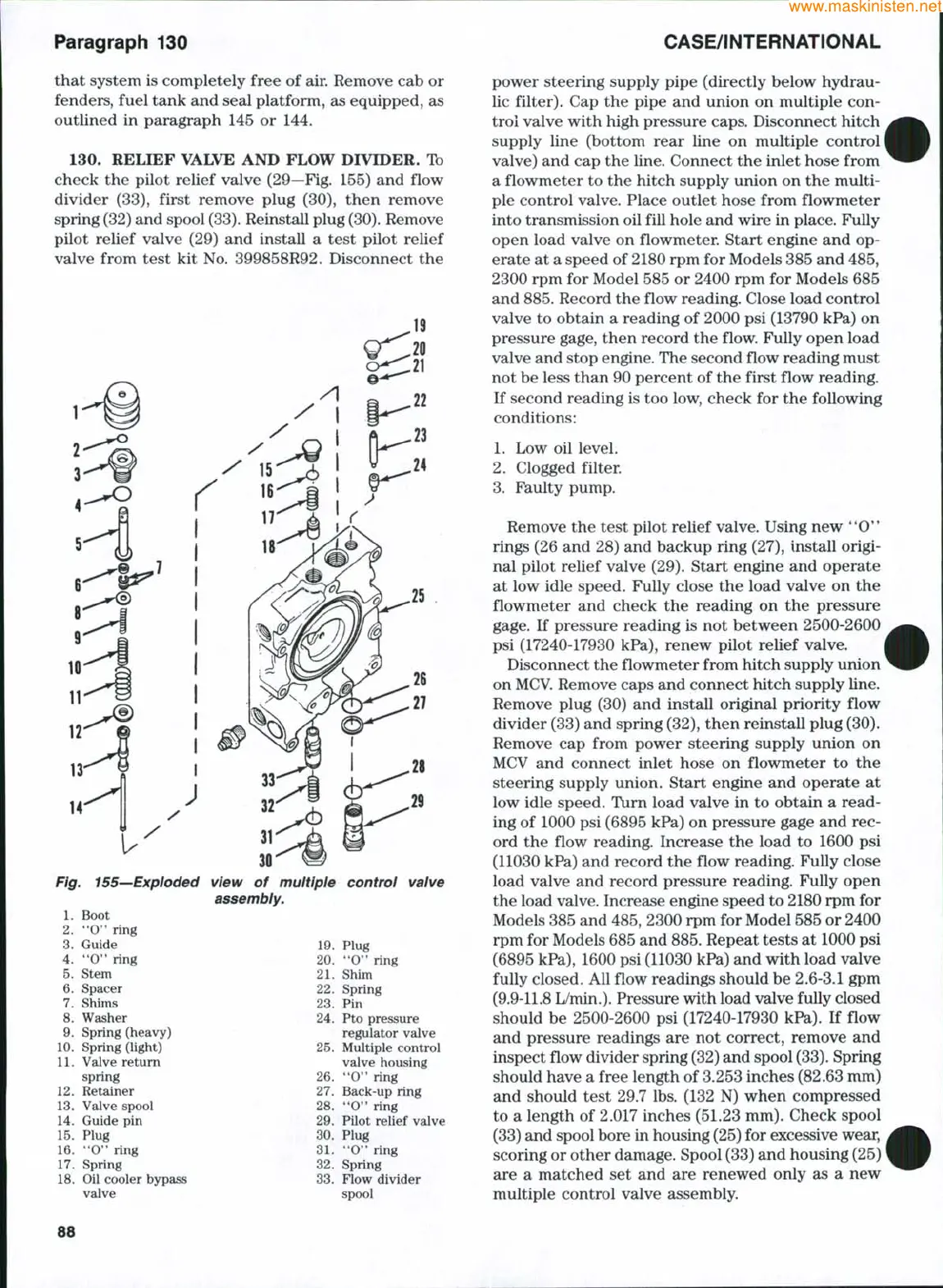
130.
RELIEF VALVE AND FLOW DIVIDER. Ib
check the pilot relief valve (29—Fig. 155) and flow
divider (33), first remove plug (30), then remove
spring (32) and spool
(33).
Reinstall plug
(30).
Remove
pilot relief valve (29) and install a test pilot relief
valve from test kit No. 399858R92. Disconnect the
Fig. 155—Exploded
1.
Boot
2.
"0*' ring
3.
Guide
4.
"0" ring
5.
Stem
6. Spacer
7.
Shims
8. Washer
9. Spring (heavy)
10.
Spring (light)
11.
Valve return
spring
12.
Retainer
13.
Valve spool
14.
Guide pin
15.
Plug
16.
*'O" ring
17.
Spring
18.
Oil cooler bypass
valve
view of multiple control valve
assembly.
19.
20.
21.
22.
23.
24.
25.
26.
27.
28.
29.
30.
31.
32.
33.
Plug
"O"
ring
Shim
Spring
Pin
Pto pressure
regulator valve
Multiple control
valve housing
"O"
ring
Back-up ring
"0"
ring
Pilot relief valve
Plug
**0"
ring
Spring
Flow divider
spool
power steering supply pipe (directly below hydrau-
lic filter). Cap the pipe and union on multiple con-
trol valve with high pressure caps. Disconnect hitch
supply line (bottom rear line on multiple control
valve) and cap the line. Connect the inlet hose from
a flowmeter to the hitch supply union on the multi-
ple control valve. Place outlet hose from flowmeter
into transmission oil fill hole and wire in place. Fully
open load valve on flowmeter. Start engine and op-
erate at a speed of 2180 rpm for Models 385 and 485,
2300 rpm for Model 585 or 2400 rpm for Models 685
and
885.
Record the flow reading. Close load control
valve to obtain a reading of 2000 psi (13790 kPa) on
pressure gage, then record the flow. Fully open load
valve and stop engine. The second flow reading must
not be less than 90 percent of the first flow reading.
If second reading is too low, check for the following
conditions:
1.
Low oil level.
2.
Clogged filter.
3.
Faulty pump.
Remove the test pilot relief valve. Using new **0"
rings (26 and 28) and backup ring (27), install origi-
nal pilot relief valve (29). Start engine and operate
at low idle speed. Fully close the load valve on the
flowmeter and check the reading on the pressure
gage.
If pressure reading is not between 2500-2600
psi (17240-17930 kPa), renew pilot relief valve.
Disconnect the flowmeter from hitch supply union
on
MCV.
Remove caps and connect hitch supply line.
Remove plug (30) and install original priority flow
divider (33) and spring (32), then reinstall plug (30).
Remove cap from power steering supply union on
MCV and connect inlet hose on flowmeter to the
steering supply union. Start engine and operate at
low idle speed. Turn load valve in to obtain a read-
ing of 1000 psi (6895 kPa) on pressure gage and rec-
ord the flow reading. Increase the load to 1600 psi
(11030 kPa) and record the flow reading. Fully close
load valve and record pressure reading. Fully open
the load valve. Increase engine speed to 2180 rpm for
Models 385 and
485,
2300 rpm for Model 585 or 2400
rpm for Models 685 and
885.
Repeat tests at 1000 psi
(6895 kPa), 1600 psi (11030 kPa) and with load valve
fully closed. All flow readings should be 2.6-3.1 gpm
(9.9-11.8 L/min.). Pressure with load valve fully closed
should be 2500-2600 psi (17240-17930 kPa). If flow
and pressure readings are not correct, remove and
inspect flow divider spring (32) and spool
(33).
Spring
should have a free length of 3.253 inches (82.63 mm)
and should test 29.7 lbs. (132 N) when compressed
to a length of 2.017 inches (51.23 mm). Check spool
(33) and spool bore in housing
(25)
for excessive wear,
scoring or other damage. Spool (33) and housing (25)
are a matched set and are renewed only as a new
multiple control valve assembly.
88