Paragraphs 76A-78
ternator and ground negative lead to adequate
ground. Start engine and operate at 1800 rpm. Volt-
meter should read between 13 and 15 volts. If volt-
age is less than 13 volts, bypass regulator and check
as outlined in paragraph 76A.
Voltage in excess of 15 volts indicates either a
grounded brush inside alternator or faulty voltage
regulator. Repair as necessary.
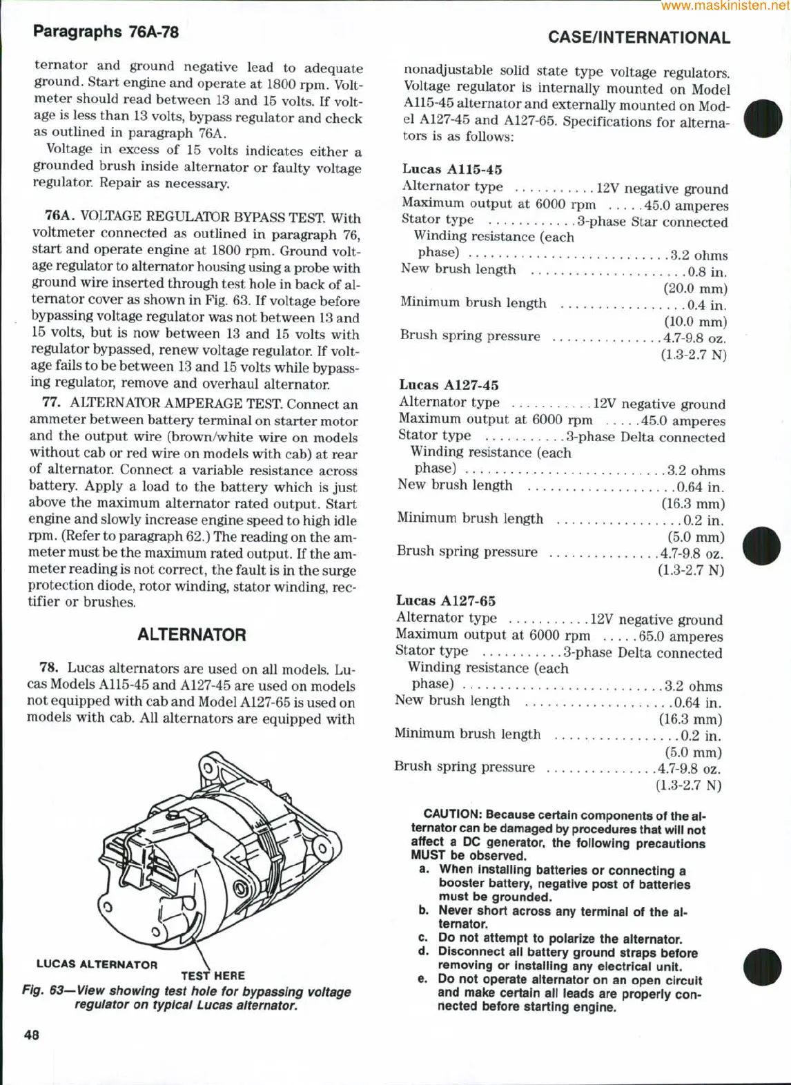
76A. VOLTAGE REGULATOR BYPASS TEST With
voltmeter connected as outlined in paragraph 76,
start and operate engine at 1800 rpm. Ground volt-
age regulator to altemator housing using a probe with
ground wire inserted through test hole in back of al-
ternator cover as shown in Fig. 63. If voltage before
bypassing voltage regulator was not between
13
and
15 volts, but is now between 13 and 15 volts with
regulator bypassed, renew voltage regulator. If volt-
age fails to be between
13
and 15 volts while bypass-
ing regulator, remove and overhaul alternator.
77.
ALTERNATOR AMPERAGE TEST. Connect an
ammeter between battery terminal on starter motor
and the output wire (brown/white wire on models
without cab or red wire on models with cab) at rear
of alternator. Connect a variable resistance across
battery. Apply a load to the battery which is just
above the maximum alternator rated output. Start
engine and slowly increase engine speed to high idle
rpm. (Refer to paragraph 62.) The reading on the am-
meter must be the maximum rated output. If the am-
meter reading is not correct, the fault is in the surge
protection diode, rotor winding, stator winding, rec-
tifier or brushes.
ALTERNATOR
78.
Lucas alternators are used on all models. Lu-
cas Models A115-45 and A127-45 are used on models
not equipped with cab and Model A127-65 is used on
models with cab. All alternators are equipped with
LUCAS ALTERNATOR
TEST HERE
Fig. 63—View showing test hole for bypassing voltage
regulator on typical Lucas aiternator.
CASE/iNTERNATiONAL
nonacyustable solid state type voltage regulators.
Voltage regulator is internally mounted on Model
A115-45 alternator and externally mounted on Mod-
el A127-45 and A127-65. Specifications for alterna-
tors is as follows:
Lucas A115-45
Alternator type 12V negative ground
Maximum output at 6000 rpm 45.0 amperes
Stator type 3-phase Star connected
Winding resistance (each
phase) 3.2 ohms
New brush length 0.8 in.
(20.0 mm)
Minimum brush length 0.4 in.
(10.0 mm)
Brush spring pressure 4.7-9.8 oz.
(1.3-2.7 N)
Lucas A127-45
Alternator type 12V negative ground
Maximum output at 6000 rpm 45.0 amperes
Stator type 3-phase Delta connected
Winding resistance (each
phase) 3.2 ohms
New brush length
.
0.64 in.
(16.3 mm)
Minimum brush length 0.2 in.
(5.0 mm)
Brush spring pressure 4.7-9.8 oz.
(1.3-2.7 N)
Lucas A127-65
Alternator type 12V negative ground
Maximum output at 6000 rpm 65.0 amperes
Stator type 3-phase Delta connected
Winding resistance (each
phase) 3.2 ohms
New brush length 0.64 in.
(16.3 mm)
Minimum brush length 0.2 in.
(5.0 mm)
Brush spring pressure .4.7-9.8 oz.
(1.3-2.7 N)
CAUTION:
Because certain components of the ai-
ternator can be damaged by procedures that wiii not
affect a DC generator, the foliowing precautions
MUST be observed.
a. When instailing batteries or connecting a
booster battery, negative post of batteries
must be grounded.
b. Never short across any terminal of the ai-
ternator.
c. Do not attempt to poiarize the aiternator.
d.
Disconnect aii battery ground straps before
removing or instaliing any electricai unit.
e. Do not operate aiternator on an open circuit
and make certain aii ieads are properiy con-
nected before starting engine.
48