Paragraph 144
CASE/INTERNATIONAL
draw detent and valve spool assembly from valve
body
(13).
Remove spacer
(10),
back-up ring
(11)
and
*
*0*'
ring from front end of valve body and
*
'0" ring
(18) from detent end of valve body. Clamp flats on
valve spool in a soft jawed vise. Use an Allen wrench
to loosen the detent retaining screw. Remove from
vise and hold assembly horizontally close to a bench
top.
Unscrew detent assembly from valve spool. See
Fig. 173. Lay detent assembly aside. Remove spring
(17-Fig. 171 or 172), poppet (16) and ball (15) from
spool
(14).
Remove collar (19) with
**0"
rings (20 and
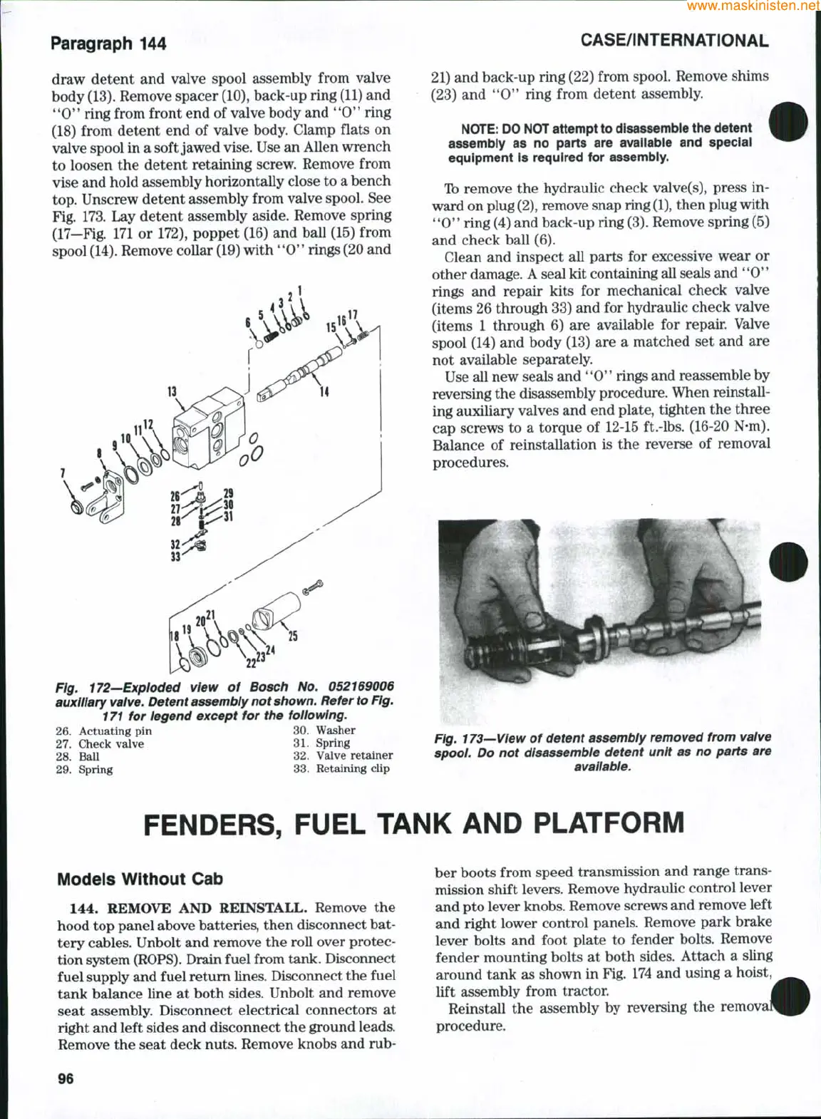
Fig. 172—Exploded view of Bosch No. 052169006
auxiliary
valve.
Detent assembly not
shown.
Refer
to
Fig.
171 for legend except for the following.
26.
Actuating pin 30. Washer
27.
Check valve 31. Spring
28.
Ball 32. Valve retainer
29.
Spring 33. Retaining clip
21) and back-up ring (22) from spool. Remove shims
(23) and **0" ring from detent assembly.
NOTE:
DO NOT attempt to disassemble the detent
assembly as no parts are available and special
equipment Is required for assembly.
Tb remove the hydraulic check valve(s), press in-
ward on plug
(2),
remove snap ring
(1),
then plug with
'*0**
ring (4) and back-up ring
(3).
Remove spring (5)
and check ball (6).
Clean and inspect all parts for excessive wear or
other damage. A seal kit containing all seals and
**0**
rings and repair kits for mechanical check valve
(items 26 through 33) and for hydraulic check valve
(items 1 through 6) are available for repair. Valve
spool (14) and body (13) are a matched set and are
not available separately.
Use all new seals and
**0"
rings and reassemble by
reversing the disassembly procedure. When reinstall-
ing auxiliary valves and end plate, tighten the three
cap screws to a torque of 12-15 ft.-lbs. (16-20 N-m).
Balance of reinstallation is the reverse of removal
procedures.
Fig. 173—View of detent assembly removed from valve
spool. Do not disassemble detent unit as no parts are
available.
FENDERS, FUEL TANK AND PLATFORM
Models Without Cab
144.
REMOVE AND REINSTALL. Remove the
hood top panel above batteries, then disconnect bat-
tery cables. Unbolt and remove the roll over protec-
tion system
(ROPS).
Drain fuel from tank. Disconnect
fuel supply and fuel return lines. Disconnect the fuel
tank balance line at both sides. Unbolt and remove
seat assembly. Disconnect electrical connectors at
right and left sides and disconnect the ground leads.
Remove the seat deck nuts. Remove knobs and rub-
ber boots from speed transmission and range trans-
mission shift levers. Remove hydraulic control lever
and pto lever knobs. Remove screws and remove left
and right lower control panels. Remove park brake
lever bolts and foot plate to fender bolts. Remove
fender mounting bolts at both sides. Attach a sUng
around tank as shown in Fig. 174 and using a hoist,
lift assembly from tractor.
Reinstall the assembly by reversing the remo^
procedure.
96