Paragraphs 138-139
CASE/INTERNATIONAL
to a torque of 80-90 ft.-lbs. (110.6-124.4 N-m). Adjust
control levers as outlined in paragraphs 131,132,133
and 134.
Models With Cab
138,
REMOVE AND REINSTALL.
Tb
remove the
hydraulic lift housing, first remove the cab as outlined
in paragraph 145. Disconnect lower end of adjusting
rod for raise rate lever, then disconnect lower adjust-
ing rods from draft and position control levers. Sep-
arate ac^usting rods from auxiliary valve control
levers, if so equipped. Disconnect pto linkage and lift
off the control levers box. Disconnect speed trans-
mission and range transmission shift linkage. Discon-
nect park brake linkage. Disconnect and remove in-
let and outlet pipes from raise rate valve. Cap or plug
all hydraulic openings immediately. Remove pto tube
and cross shaft. Disconnect and remove remote valve
pipes and remote couplers. Disconnect and remove
pipe from unloading and flow control valve. Discon-
nect and remove any other necessary hydraulic tubes.
Remove third link from sensing bracket and discon-
nect lift links from upper lift arms. Unbolt lift hous-
ing, attach a sling and hoist, then lift housing from
tractor.
Thoroughly clean mounting surfaces and apply a
1/8 inch (3 mm) bead of Loctite 515 on the center of
the mounting surface of transmission case. Install
three new Tbflon seals in grooves in face of transmis-
sion. Reinstall hydraulic housing over the two locat-
ing dowels. Tighten the 3/8 inch cap screws to a
torque of
33-37
ft.-lbs. (45.6-51.5
N-m)
and the 1/2 inch
cap screws to a torque of 80-90 ft.-lbs. (110.6-124.4
N-m).
Complete installation by reversing the removal
procedure. Adjust control levers as outlined in para-
graphs 131, 132, 133 and 134.
CYLINDER AND VALVE UNIT
All Models
139.
R&R AND OVERHAUL.
Tb
remove the work
cylinder and valve assembly, first remove the lift unit
from tractor as outlined in paragraph
137
or
138.
Turn
lift unit upside down on a work bench. Disconnect
control linkage from main valve and other linkage.
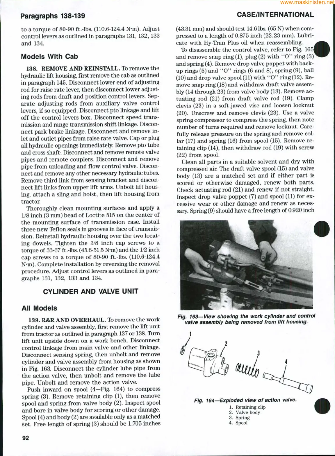
Disconnect sensing spring, then unbolt and remove
cylinder and valve assembly from housing as shown
in Fig. 163. Disconnect the cylinder lube pipe from
the action valve, then unbolt and remove the lube
pipe.
Unbolt and remove the action valve.
Push inward on spool (4—Fig. 164) to compress
spring (3). Remove retaining clip (1), then remove
spool and spring from valve body (2). Inspect spool
and bore in valve body for scoring or other damage.
Spool (4) and body (2) are available only as a matched
set. Free length of spring (3) should be 1.705 inches
(43.31 mm) and should test
14.6 lbs.
(65
N)
when com-
pressed to a length of 0.875 inch (22.23 mm). Lubri-
cate with Hy-Tran Plus oil when reassembling.
Tb disassemble the control valve, refer to Fig. 16
and remove snap ring (1), plug (2) with
**0**
ring (3)
and spring
(4).
Remove drop valve poppet with back-
up rings (5) and
**0*'
rings (6 and 8), spring (9), ball
(10) and drop valve spool
(11)
with
'*0**
ring
(12).
Re-
move snap ring
(18)
and withdraw draft valve assem-
bly (14 through 23) from valve body
(13).
Remove ac-
tuating rod (21) from draft valve rod (19). Clamp
clevis (23) in a soft jawed vise and loosen locknut
(20).
Unscrew and remove clevis (23). Use a valve
spring compressor to compress the spring, then note
number of turns required and remove locknut. Care-
fully release pressure on the spring and remove col-
lar (17) and spring (16) from spool (15). Remove re-
taining clip (14), then withdraw rod (19) with screw
(22) from spool.
Clean all parts in a suitable solvent and dry with
compressed air. The draft valve spool (15) and valve
body (13) are a matched set and if either part is
scored or otherwise damaged, renew both parts.
Check actuating rod (21) and renew if not straight.
Inspect drop valve poppet (7) and spool (11) for ex-
cessive wear or other damage and renew as neces-
sary. Spring
(9)
should have a free length of 0.920 inch
Fig. 163—View showing the work cylinder and control
valve assembly being removed from lift housing.
Fig. 164—Exploded view of action valve.
1.
Retaining clip
2.
Valve body
3.
Spring
4.
Spool
92
 Loading...


