SERVICE MANUAL
Paragraph 145
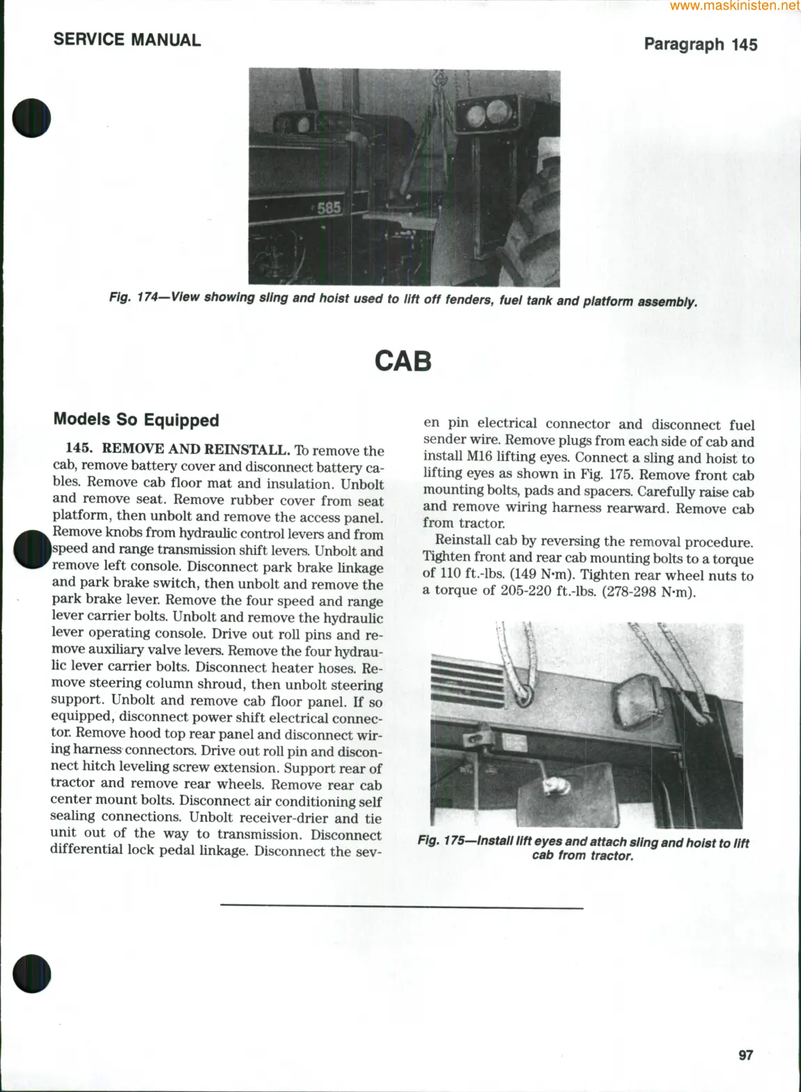
Fig, 174—View showing sling and hoist used to lift off fenders, fuel tank and platform assembly.
CAB
Models So Equipped
145.
REMOVE AND REINSTALL. Ib remove the
cab,
remove battery cover and disconnect battery ca-
bles.
Remove cab floor mat and insulation. Unbolt
and remove seat. Remove rubber cover from seat
platform, then unbolt and remove the access panel.
Remove knobs from hydraulic control levers and from
ipeed and range transmission shift levers. Unbolt and
remove left console. Disconnect park brake linkage
and park brake switch, then unbolt and remove the
park brake lever. Remove the four speed and range
lever carrier
bolts.
Unbolt and remove the hydraulic
lever operating console. Drive out roll pins and re-
move auxiliary valve levers. Remove the four hydrau-
lic lever carrier bolts. Disconnect heater hoses. Re-
move steering column shroud, then unbolt steering
support. Unbolt and remove cab floor panel. If so
equipped, disconnect power shift electrical connec-
tor. Remove hood top rear panel and disconnect wir-
ing harness connectors. Drive out roll pin and discon-
nect hitch leveling screw extension. Support rear of
tractor and remove rear wheels. Remove rear cab
center mount bolts. Disconnect air conditioning self
sealing connections. Unbolt receiver-drier and tie
unit out of the way to transmission. Disconnect
differential lock pedal linkage. Disconnect the sev-
en pin electrical connector and disconnect fuel
sender
wire.
Remove plugs from each side of cab and
install M16 lifting eyes. Connect a sling and hoist to
lifting eyes as shown in Fig. 175. Remove front cab
mounting
bolts,
pads and spacers. Carefully raise cab
and remove wiring harness rearward. Remove cab
from tractor.
Reinstall cab by reversing the removal procedure.
Tighten front and rear cab mounting bolts to a torque
of 110 ft.-lbs. (149 N-m). Tighten rear wheel nuts to
a torque of 205-220 ft.-lbs. (278-298 N-m).
Fig. 175—Install lift eyes and attach sling and hoist to lift
cab from
tractor.
97