SERVICE MANUAL
Paragraphs 72-76
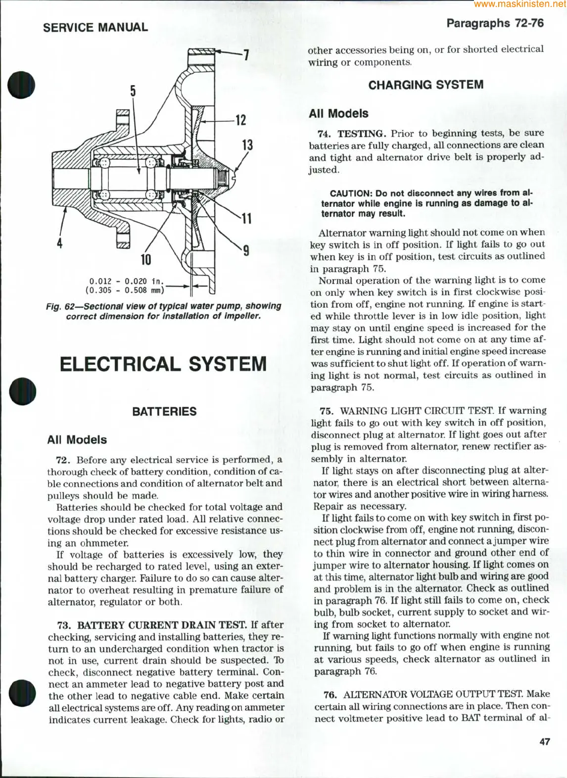
0.012 - 0.020 In.
(0.305 - 0.508 mm)'
Fig. 62—Sectional view of typicai water pump, showing
correct dimension for installation of impeller.
ELECTRICAL SYSTEM
BATTERIES
All Modeis
72.
Before any electrical service is performed, a
thorough check of battery condition, condition of ca-
ble connections and condition of alternator belt and
pulleys should be made.
Batteries should be checked for total voltage and
voltage drop under rated load. All relative connec-
tions should be checked for excessive resistance us-
ing an ohmmeter.
If voltage of batteries is excessively low, they
should be recharged to rated level, using an exter-
nal battery charger. Failure to do so can cause alter-
nator to overheat resulting in premature failure of
alternator, regulator or both.
73.
BATTERY CURRENT DRAIN TEST. If after
checking, servicing and installing batteries, they re-
turn to an undercharged condition when tractor is
not in use, current drain should be suspected. Ib
check, disconnect negative battery terminal. Con-
nect an ammeter lead to negative battery post and
the other lead to negative cable end. Make certain
all electrical systems are off. Any reading on ammeter
indicates current leakage. Check for lights, radio or
other accessories being on, or for shorted electrical
wiring or components.
CHARGING SYSTEM
Aii Modeis
74.
TESTING. Prior to beginning tests, be sure
batteries are fully charged, all connections are clean
and tight and alternator drive belt is properly ad-
justed.
CAUTION:
Do not disconnect any wires from ai-
ternator whiie engine is running as damage to ai-
ternator may result.
Alternator waming light should not come on when
key switch is in off position. If light fails to go out
when key is in off position, test circuits as outlined
in paragraph 75.
Normal operation of the warning light is to come
on only when key switch is in first clockwise posi-
tion from off, engine not running. If engine is start-
ed while throttle lever is in low idle position, light
may stay on until engine speed is increased for the
first time. Light should not come on at any time af-
ter engine is running and initial engine speed increase
was sufficient to shut light off. If operation of warn-
ing light is not normal, test circuits as outlined in
paragraph 75.
75.
WARNING LIGHT CIRCUIT TEST. If warning
light fails to go out with key switch in off position,
disconnect plug at alternator. If light goes out after
plug is removed from alternator, renew rectifier as-
sembly in alternator.
If light stays on after disconnecting plug at alter-
nator, there is an electrical short between alterna-
tor wires and another positive wire in wiring hamess.
Repair as necessary.
If light fails to come on with key switch in first po-
sition clockwise from off, engine not running, discon-
nect plug from alternator and connect a jumper wire
to thin wire in connector and ground other end of
jumper wire to alternator housing. If light comes on
at this time, altemator light bulb and wiring are good
and problem is in the alternator. Check as outlined
in paragraph 76. If light still fails to come on, check
bulb,
bulb socket, current supply to socket and wir-
ing from socket to altemator.
If waming light functions normally with engine not
running, but fails to go off when engine is running
at various speeds, check alternator as outlined in
paragraph 76.
76.
ALTERNATOR VOLTAGE OUTPUT
TEST.
Make
certain all wiring connections are in place. Then con-
nect voltmeter positive lead to BAT terminal of al-
47
 Loading...


