SERViCE MANUAL
Paragraphs 34-35
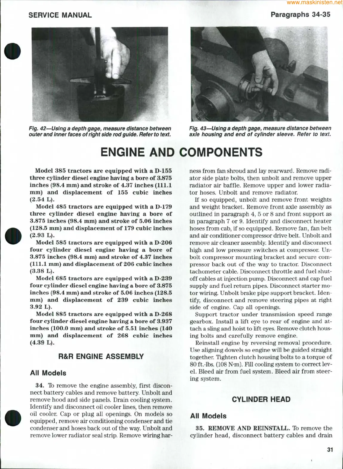
Fig. 42—Using a depth gage, measure distance between
outer and inner
faces
of right
side
rod guide. Refer
to
text.
Fig. 43—Using a depth gage, measure distance between
axle housing and end of cyiinder sieeve. Refer to
text.
ENGINE AND COMPONENTS
Model 385 tractors are equipped with a D-155
three cylinder diesel engine having a bore of 3.875
inches (98.4 mm) and stroke of 4.37 inches (111.1
mm) and displacement of 155 cubic inches
(2.54 L).
Model 485 tractors are equipped with a D-179
three cylinder diesel engine having a bore of
3.875 inches (98.4 mm) and stroke of 5.06 inches
(128.5 mm) and displacement of 179 cubic inches
(2.93 L).
Model 585 tractors are equipped with a D-206
four cylinder diesel engine having a bore of
3.875 inches (98.4 mm) and stroke of 4.37 inches
(111.1 mm) and displacement of 206 cubic inches
(3.38 L).
Model 685 tractors are equipped with a D-239
four cylinder diesel engine having a bore of 3.875
inches (98.4 mm) and stroke of 5.06 inches (128.5
mm) and displacement of 239 cubic inches
3.92 L).
Model 885 tractors are equipped with a D-268
four cylinder diesel engine having a bore of 3.937
inches (100.0 mm) and stroke of 5.51 inches (140
mm) and displacement of 268 cubic inches
(4.39 L).
R&R ENGiNE ASSEMBLY
Aii Modeis
34.
Ib remove the engine assembly, first discon-
nect battery cables and remove battery. Unbolt and
remove hood and side panels. Drain cooling system.
Identify and disconnect oil cooler lines, then remove
oil cooler. Cap or plug all openings. On models so
equipped, remove air conditioning condenser and tie
condenser and hoses back out of the way. Unbolt and
remove lower radiator seal strip. Remove wiring har-
ness from fan shroud and lay rearward. Remove radi-
ator side plate bolts, then unbolt and remove upper
radiator air baffle. Remove upper and lower radia-
tor hoses. Unbolt and remove radiator.
If so equipped, unbolt and remove front weights
and weight bracket. Remove front axle assembly as
outlined in paragraph 4, 5 or 8 and front support as
in paragraph 7 or 9. Identify and disconnect heater
hoses from cab, if so equipped. Remove fan, fan belt
and air conditioner compressor drive belt. Unbolt and
remove air cleaner assembly. Identify and disconnect
high and low pressure switches at compressor Un-
bolt compressor mounting bracket and secure com-
pressor back out of the way to tractor. Disconnect
tachometer cable. Disconnect throttle and fuel shut-
off cables at ir\jection pump. Disconnect and cap fuel
supply and fuel retum pipes. Disconnect starter mo-
tor wiring. Unbolt brake pipe support bracket. Iden-
tify, disconnect and remove steering pipes at right
side of engine. Cap all openings.
Support tractor under transmission speed range
gearbox. Install a lift eye to rear of engine and at-
tach a sling and hoist to lift
eyes.
Remove clutch hous-
ing bolts and carefully remove engine.
Reinstall engine by reversing removal procedure.
Use aligning dowels so engine will be guided straight
together. Tighten clutch housing bolts to a torque of
80 ft.-lbs. (108
N-m).
Fill cooling system to correct lev-
el.
Bleed air from fuel system. Bleed air from steer-
ing system.
CYLiNDER HEAD
Aii Modeis
35.
REMOVE AND REINSTALL. Ib remove the
cylinder head, disconnect battery cables and drain
31